
A heating and curing furnace for anti-corrosion treatment of steel components

A technology of anti-corrosion treatment and heat curing, applied in lighting and heating equipment, drying solid materials, metal material coating technology, etc., can solve the problems of concrete structure damage, environmental pollution, thin anti-corrosion coating, etc., and achieve high energy saving level, Quick and easy operation

Active Publication Date: 2018-11-30
吉林鑫达钢铁有限公司
View PDF5 Cites 0 Cited by
  • Summary
  • Abstract
  • Description
  • Claims
  • Application Information

AI Technical Summary

Problems solved by technology

The embedded parts of bridges with reinforced concrete structure are prone to corrosion and damage the concrete structure of the bridge due to long-term exposure to various corrosion-causing factors such as freezing damage, chemical corrosion, steel corrosion, and alkali-aggregate reaction; especially due to humidity The effect of carbon dioxide, temperature and carbon dioxide will cause carbonization of concrete, and the effect of corrosive media such as oxygen, sulfur dioxide and chlorine will further aggravate the corrosion of bridge embedded parts and the damage of concrete structure
Traditional anti-corrosion processes such as electro-galvanizing, electro-cadmium electro-plating, hot-dip galvanizing, hot-spraying zinc, and phosphating not only have thin anti-corrosion coatings, poor compactness and poor impermeability, but also cause serious pollution to the environment by waste water, waste gas, and waste residues associated with traditional anti-corrosion processes.

Method used


Image

  • A heating and curing furnace for anti-corrosion treatment of steel components
  • A heating and curing furnace for anti-corrosion treatment of steel components

Examples


Embodiment Construction

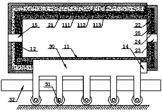
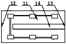
[0018] refer to Figure 1 to Figure 2 , Figure 1 to Figure 2 It is a structural schematic diagram of a specific embodiment of the present invention.

[0019] Such as figure 1 and figure 2 As shown, a heating and curing furnace for surface anticorrosion treatment of steel members includes a fixed heating outer furnace for heating and heat preservation, and the fixed heating outer furnace includes a fixed heating outer sleeve 11 of tubular structure, and the fixed heating outer sleeve One end of 11 is provided with a fixed heating end wall 12, and the other end of the fixed heating outer sleeve 11 is a heating inner tank inlet and outlet 13; the fixed heating end wall 12 is provided with a purified gas discharge port 15; the fixed heating outer sleeve 11 and the fixed heating end wall 12 are integrated, and the fixed heating outer sleeve 11 and the fixed heating end wall 12 are sequentially composed of a glass fiber cloth filling layer 111, a heat-insulating ceramic layer 1...


PUM


Abstract

The invention discloses a heating curing furnace for anti-corrosion treatment of a steel member surface. The heating curing furnace comprises a fixed heating outer furnace and a movable heating inner tank, wherein the fixed heating outer furnace includes a fixed heating outer sleeve pipe; a fixed heating end wall is disposed on one end of the fixed heating outer sleeve pipe, and an inlet / outlet of the heating inner tank is formed in the other end of the fixed heating outer sleeve pipe; the movable heating inner tank includes a movable heated inner sleeve pipe; a movable closed insulation cover is disposed on one end of the movable heated inner sleeve pipe; a movable support base is disposed at the bottom of the movable heating inner tank; an upper end of the movable support base is located in the fixed heating outer sleeve pipe and is connected with the bottom of the movable heating inner tank; a lower end of the movable support base is located below the outside of the fixed heating outer sleeve pipe; and a base movable hollow groove for enabling the movable support base to pass through is disposed in the bottom of the fixed heating outer sleeve pipe. The heating curing furnace is suitable for heating curing of a surface anti-corrosion treatment layer on a large-size steel member and is high in thermal insulation properties, that is, high in energy-saving level.

Description

technical field [0001] The invention relates to the technical field of steel component surface anticorrosion treatment equipment, in particular to a heating and curing furnace for steel component surface anticorrosion treatment. Background technique [0002] Every year, the world's steel corrosion loss accounts for more than 10% of the total steel output, and the economic loss caused by corrosion in industrially developed countries accounts for more than 2% to 4% of the total output value of the national economy; research and develop advanced anti-corrosion technology to reduce economic losses caused by corrosion Prolonging the service life of steel and other metal materials and equipment is of great significance to promoting the development of advanced technology, cutting-edge science and defense industry, as well as the sustainable and coordinated development of the national economy and social environment. The embedded parts of bridges with reinforced concrete structure ar...

Claims


Application Information

Patent Timeline
Patent Type & Authority Patents(China)
IPC IPC(8): C23C22/82F26B25/00F26B25/06
CPCC23C22/82F26B25/005F26B25/06
Inventor 晋华明
Owner 吉林鑫达钢铁有限公司
Learn More