Earth-rock filling structure and construction method for pit and pond-type depressions

A technology for earthwork and depressions, applied in the field of foundation and slope treatment, can solve problems such as uneven underground drainage and settlement, and achieve the effects of simple construction procedures, good application prospects, and wide promotion

Active Publication Date: 2018-01-16
广州中南民航工程咨询监理有限公司
View PDF5 Cites 0 Cited by
  • Summary
  • Abstract
  • Description
  • Claims
  • Application Information

AI Technical Summary

Problems solved by technology

[0004] In view of this, the purpose of the present invention is to provide a pit pond type depression earthwork filling structure and construction method to solve the two technical problems of underground drainage and uneven settlement of the depression filling body after construction

Method used


Image

  • Earth-rock filling structure and construction method for pit and pond-type depressions
  • Earth-rock filling structure and construction method for pit and pond-type depressions
  • Earth-rock filling structure and construction method for pit and pond-type depressions

Examples


Embodiment 1

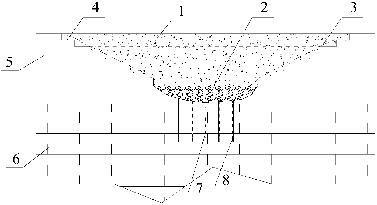
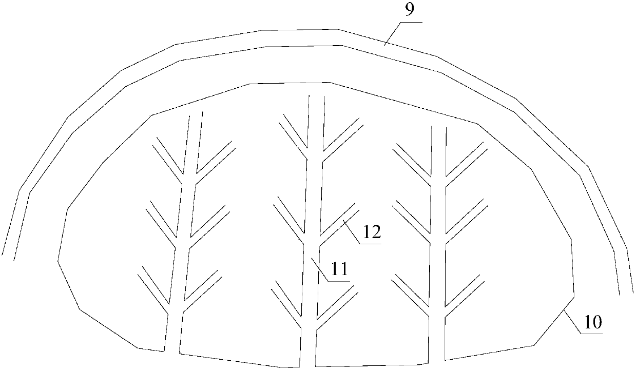
[0033] A pit and pond type depression earthwork filling structure, characterized in that it includes filling soil 1, a pit bottom broken rock water cushion 2, a surrounding bedrock 5 of the depression, a pit bottom rock layer 6, a bottom water guide hole 7, and a water guide hole The filled gravel 8, the intercepting ditch 9 around the filling body and the main drainage ditch 11 on the surface of the filling body.

[0034] The filling 1, the water accumulation cushion 2 of broken stones at the bottom of the pit and the gravel 8 filled in the water guide hole constitute a filling body.

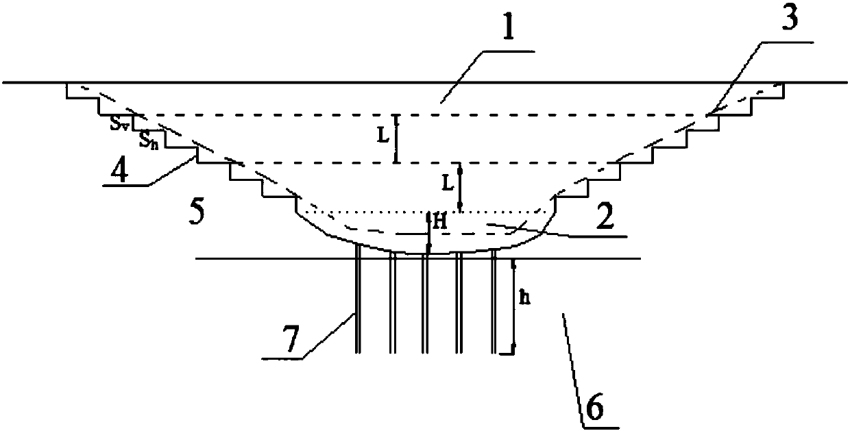
[0035] The middle of the bedrock 5 around the depression is a depression. The side wall of the depression is a stepped excavation surface 4 . The bottom of the depression is the rock formation 6 at the bottom of the pit. The height of each step of the stepped excavation surface 4 is ≤1m, and the overall slope of the stepped excavation surface 4 is 1:1˜1:2. The bottom of the depression has se...

Embodiment 2

[0048]This embodiment discloses a construction method for earthwork filling structure of pit and pond type depression, which is characterized in that it includes the following steps:

[0049] S1: The depression is the enclosed pit or ditch on the surface. Drain the accumulated water in the pit, remove the silt and soil from the bottom and side walls of the pit to the bedrock, and excavate the side wall of the pit to form a stepped slope. Excavation bench height S v Less than 1m, and the overall slope S v / S h 1:1~1:2. Clean up the earth and rock piled up at the bottom of the pit due to the excavation side wall again.

[0050] S2: Arrange and drill water guide holes at the bottom of the pit to the permeable layer of the rock formation at the bottom of the pit. The water guide holes should be arranged in the low-lying part of the pit, and can be arranged in a plum blossom shape at a certain interval. The diameter of the water guide hole is ≥ 100mm, and the depth h of the ro...


PUM


Abstract

The invention discloses a pit-pond type depression earthwork and stonework filling structure and a construction method. The structure comprises filling, a pit bottom fragment rock ponding cushion layer, depression peripheral bed rocks, bottom water guiding holes, gravel used for filling the water guiding holes, a catchwater around a filling body and a filling body main surface drainage ditch. The construction method of the structure comprises the steps that unwatering is conducted; side walls are dug into stepped slope faces; the water guiding holes are drilled; fragment rocks of the ponding cushion layer are stuffed and compacted; the filling is stuffed and tamped or compacted; and the drainage ditch is constructed. The problem of accumulated water drainage at the bottom of pit-pond type depression filling bodies such as ponds and ditches is solved, the stability and deformation performance of the filling bodies are improved, the work procedures are simple, the cost of adopted materials is low, the structure has good application prospects, and the structure and the method are particularly suitable for stratums with the relatively low pit bottom rock formation permeability coefficient.

Description

technical field [0001] The invention relates to a foundation and slope treatment technology. Background technique [0002] Mine dumps are piled up, airports, highways and railway traffic construction and other fields may encounter earthwork filling construction of ponds, deep ditches and other pit-type depressions, especially in mountainous areas. There are two prominent engineering hidden dangers in this type of filling body: 1. A water accumulation area may be formed at the bottom of the pit, especially when the bottom rock formation has poor water permeability. The water at the bottom not only produces a large buoyancy force on the upper filling, but also seriously reduces the shear strength of the saturated soil in the bottom water area, which in turn induces a catastrophe of the filling soil. A typical example is that at 11:40 on December 20, 2015, a landslide occurred in Hengtaiyu Industrial Park, Fenghuang Community, Guangming New District, Shenzhen, Guangdong Provin...

Claims


Application Information

Patent Timeline
Patent Type & Authority Patents(China)
IPC IPC(8): E02D17/18E02D19/02E02D19/10
CPCE02D17/18E02D19/02E02D19/10
Inventor 黄达孟蒙李斌曾彬岑夺丰
Owner 广州中南民航工程咨询监理有限公司
Why Eureka
Try Eureka