Solar insulation box for outdoor electronic equipment in alpine region

A technology of high-cold regions and external electronics, which is applied to solar collectors, solar thermal energy, solar thermal power generation and other directions in specific environments, can solve problems such as power consumption, complex structure, and impact on equipment operation, to prevent theft and destruction, guarantee The effect of safety and simplified structure

Inactive Publication Date: 2016-10-26
HARBIN UNIV OF SCI & TECH +1
View PDF10 Cites 0 Cited by
  • Summary
  • Abstract
  • Description
  • Claims
  • Application Information

AI Technical Summary

Problems solved by technology

[0002] In order to ensure the stability and reliability of the power system, it is necessary to ensure the normal operation of electronic equipment. However, in some areas with harsh environments, such as alpine areas, electronic equipment exposed outdoors will often be in a low temperature state, which will cause damage to equipment operation. The impact of the equipment will cause the equipment to not work normally, and even shorten the service life of the equipment; at the same time, the failure of electronic equipment under low temperature conditions will cause damage to the stable, reliable and continuous operation of the power system.
[0003] At present, the environmental temperature control measures for outdoor electronic equipment in alpine regions are all electric heating methods, which require external power supply or use new energy power supply. The structure is complicated, the cost is high, the power consumption is high, and it is not environmentally friendly, and it is not easy to install and maintain.
In addition, the insulation part of outdoor electronic equipment is usually made into an integrated structure, which is not conducive to installation, disassembly and maintenance

Method used


Image

  • Solar insulation box for outdoor electronic equipment in alpine region
  • Solar insulation box for outdoor electronic equipment in alpine region
  • Solar insulation box for outdoor electronic equipment in alpine region

Examples


Embodiment Construction

[0022] The present invention will be described in further detail below in conjunction with the drawings:

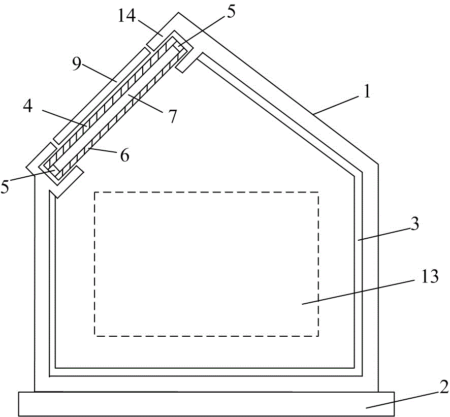
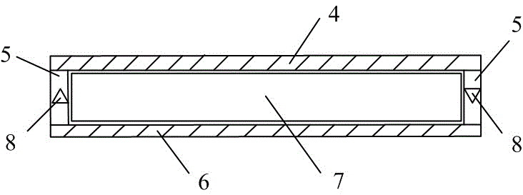
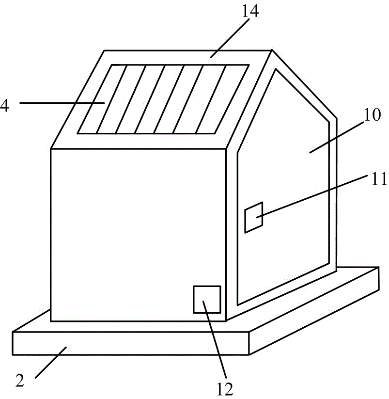
[0023] Such as figure 1 As shown, the box (1) is installed and fixed by the lower fixing mechanism (2). In order to effectively prevent theft, it can be welded on-site, which does not affect the maintenance of the incubator, especially the installation and installation of electronic equipment (13). take out. A layer of thermal insulation material, namely thermal insulation module (3), close to the inner wall of the box body (1) is used for thermal insulation. The box is designed in the shape of a small house. The roof has two slopes, which are convenient for collecting solar energy and have rainproof function. Install a protective edge (14) on the sunny slope to protect the solar heat collection module (4) and the heat dissipation module (6) When installing, the solar heat collection module (4) faces outwards, the heat dissipation module (3) faces inwards, and the reflectiv...


PUM


Abstract

The invention discloses a solar insulation box for outdoor electronic equipment in an alpine region, and belongs to the technical field of solar utilization equipment. The device comprises a box body, a fixing structure, an insulation module, a solar heat collecting module, connecting pipes and a cooling module. The solar heat collecting module and the cooling module are integrated; liquid in a heat collecting pipe is heated through acquiring solar energy; the interior of the box body is heated by using natural convection; and the installation, the disassembly and the maintenance are convenient. In addition, the box body is provided with a movable door, a door lock and a protective edge; elements and electronic equipment in the box can be protected; and the placement and the removal of the electronic equipment are convenient. The solar insulation box directly uses the solar energy for heating the liquid, omits conversion, energy storage and electric heating modules, effectively saves the cost, is simple in structure, and can be widely applied to insulation and protection of the electronic equipment in the alpine region.

Description

Technical field [0001] The invention relates to a solar thermal insulation box for outdoor electronic equipment in alpine regions. It belongs to the technical field of solar energy utilization equipment. Background technique [0002] In order to ensure the stability and reliability of the power system, it is necessary to ensure the normal operation of electronic equipment. However, in some areas with harsh environments, such as high-cold areas, electronic equipment exposed outdoors will often be in a low temperature state, which will affect the operation of the equipment. This will cause the equipment to not work normally and even shorten the service life of the equipment. At the same time, the failure of electronic equipment under low temperature conditions will cause harm to the stable, reliable and continuous operation of the power system. [0003] At present, the environmental temperature control measures for outdoor electronic equipment in high-cold areas are all electric hea...

Claims


Application Information

Patent Timeline
Patent Type & Authority Applications(China)
IPC IPC(8): F24J2/04F24J2/46
CPCF24S20/67F24S40/10F24S80/00Y02E10/40
Inventor 周封刘小可郝婷崔博闻李隆
Owner HARBIN UNIV OF SCI & TECH
Why Eureka
Try Eureka