Dynamic simulation engine testing system and method

A technology of dynamic simulation and test system, applied in the direction of engine test, general control system, control/regulation system, etc., can solve the problem of inability to accurately simulate the performance of the whole vehicle

Active Publication Date: 2016-10-26
中检西部检测有限公司
View PDF8 Cites 10 Cited by
  • Summary
  • Abstract
  • Description
  • Claims
  • Application Information

AI Technical Summary

Problems solved by technology

With the development of technology and the need to shorten the development cycle, it is necessary ...

Method used


Image

  • Dynamic simulation engine testing system and method
  • Dynamic simulation engine testing system and method
  • Dynamic simulation engine testing system and method

Examples


Embodiment 1

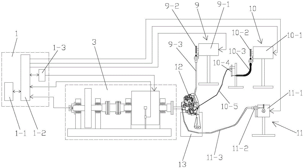
[0115] Such as figure 1 As shown, the dynamic simulation engine test system of the present invention comprises a dynamic simulation dynamometer 3, a sensing detection system, a control system 1 and an engine stand 13 for installing the engine to be tested 12, and for operating the engine to be tested 12 Accelerator operating mechanism 9, clutch operating mechanism 10 and shift operating mechanism 11;

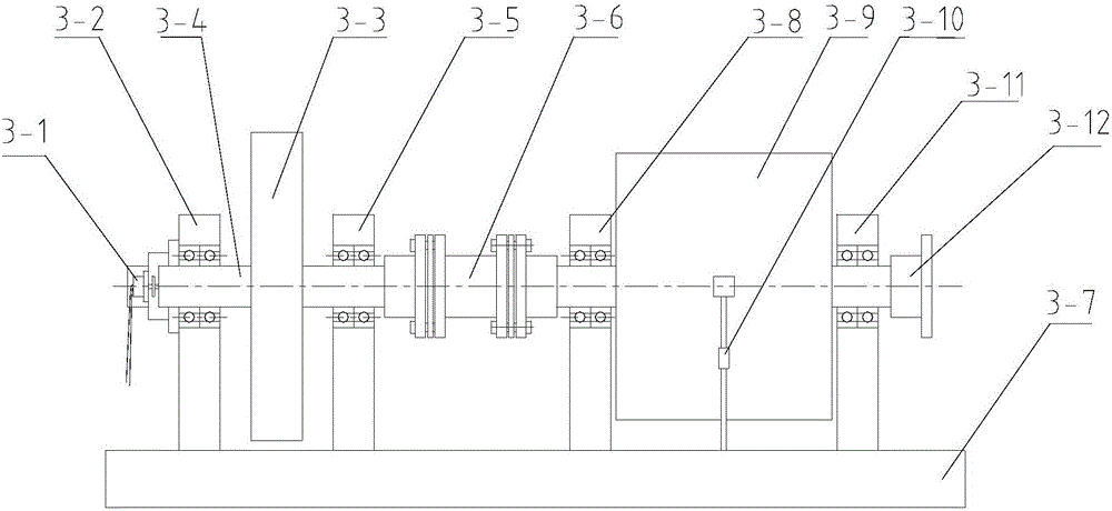
[0116] combine image 3 , the dynamic simulation dynamometer 3 includes a base 3-7 and a first inertia flywheel bearing support 3-2 fixedly connected to the base 3-7, a second inertia flywheel bearing support 3-5, a first motor bearing support 3 -8 and the second motor bearing support 3-11, the first inertia flywheel bearing support 3-2 and the second inertia flywheel bearing support 3-5 are equipped with a flywheel shaft 3-4, located at the first inertia flywheel bearing A flywheel shaft 3-4 between the support 3-2 and the second inertia flywheel bearing support 3-5 is connec...

Embodiment 2

[0185] Such as Figure 6 , Figure 7 and Figure 8 As shown, the difference between this embodiment and Embodiment 1 is that the inertia flywheel is a flange type inertia flywheel 3-13, and the flange type inertia flywheel 3-13 includes a disc-shaped flange type flywheel body 3- 131 and the flanged flywheel installation hole 3-132 that is arranged at the center of the flanged flywheel body 3-131 and is used to connect the flywheel shaft 3-4, the two sides of the flanged flywheel body 3-131 The tops are all provided with circular weight-reducing process tanks 3-133. All the other structures are the same as in Example 1. By setting the weight-reducing process tank 3-133, a large-radius inertial flywheel can be realized with less material, and then the simulation of a larger inertia can be realized, which saves materials and costs, and expands the application range.

[0186] The dynamic simulation engine test method of this embodiment is the same as that of Embodiment 1.


PUM


Abstract

The invention discloses a dynamic simulation engine testing system, and the system comprises a dynamic simulation dynamometer, a sensing detection system, a control system, an engine rack, a throttle operating mechanism, a clutch operating mechanism, and a gear shift operating mechanism. The dynamic simulation dynamometer comprises a pedestal, a first inertia flywheel bearing support, a second inertia flywheel bearing support, a first motor bearing support, and a second motor bearing support. The first inertia flywheel bearing support and the second inertia flywheel bearing support are respectively provided with a flywheel shaft, and the flywheel shafts are connected with inertia flywheels. A dynamometer motor is disposed between the first motor bearing support and the second motor bearing support. End parts of the flywheel shafts are connected with a coder. The housing of the dynamometer motor is provided with a force sensor. The control system comprises a main control computer, a PLC module, and a frequency converter. The sensing detection system comprises a fuel consumption meter. The invention also discloses a dynamic simulation engine testing method. The system is convenient to install and use, is high in working reliability, and is high in practicality.

Description

technical field [0001] The invention belongs to the technical field of engine testing, and in particular relates to a dynamic simulation engine testing system and method. Background technique [0002] Traditional engine test systems are generally used to measure engine power, torque, fuel consumption and other parameters. With the development of technology and the need to shorten the development cycle, it is necessary to simulate the performance (vehicle speed, acceleration performance, etc.) Simulate vehicle performance. Contents of the invention [0003] The technical problem to be solved by the present invention is to provide a simple structure, novel and reasonable design, convenient use, low implementation cost, high working reliability, long service life, and can be effectively installed on the engine stand in view of the above-mentioned deficiencies in the prior art. Carry out the simulation of vehicle performance, reduce the cost of development and test, and a dy...

Claims


Application Information

Patent Timeline
IPC IPC(8): G01M15/02G05B19/05
CPCG01M15/02G05B19/058G05B2219/163
Inventor 杨建伟
Owner 中检西部检测有限公司
Why Eureka
Try Eureka