Fiber winding system and automatic control method

A fiber machine and winding technology, which is applied in the field of fiber winding machine system and automatic control, can solve the problems of inaccurate length calculation, lower real-time performance, and unsatisfactory performance, and achieve simple control structure, improved production efficiency, and high fiber winding efficiency Effect

Inactive Publication Date: 2016-10-26
GUANGXUN SCI & TECH WUHAN
View PDF7 Cites 12 Cited by
  • Summary
  • Abstract
  • Description
  • Claims
  • Application Information

AI Technical Summary

Problems solved by technology

There are many shortcomings in manual winding, such as low efficiency, inaccurate length calculation, etc.
Although the single-chip microcomputer control method can realize automatic control, due to the serial working mode of the single-chip microcomputer, the real-time performance of the control is greatly reduced, and the fiber tension control is also unstable, which may cause adverse effects on the quality of the wound optical fiber ring.
The optical fiber rewinding machines currently on the market have the advantages of powerful functions, high precision in length calculation and cable arrangement, but most of them are bulky and are mostly suitable for winding optical fiber cables, which cannot meet the needs of different small sizes in the optical module production process. , Fiber ring requirements of different fiber lengths

Method used


Image

  • Fiber winding system and automatic control method
  • Fiber winding system and automatic control method
  • Fiber winding system and automatic control method

Examples


Embodiment Construction

[0034] The following will clearly and completely describe the technical solutions in the embodiments of the present invention with reference to the accompanying drawings in the embodiments of the present invention. Obviously, the described embodiments are only some, not all, embodiments of the present invention. Based on the embodiments of the present invention, all other embodiments obtained by persons of ordinary skill in the art without making creative efforts belong to the protection scope of the present invention.

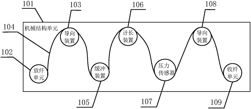
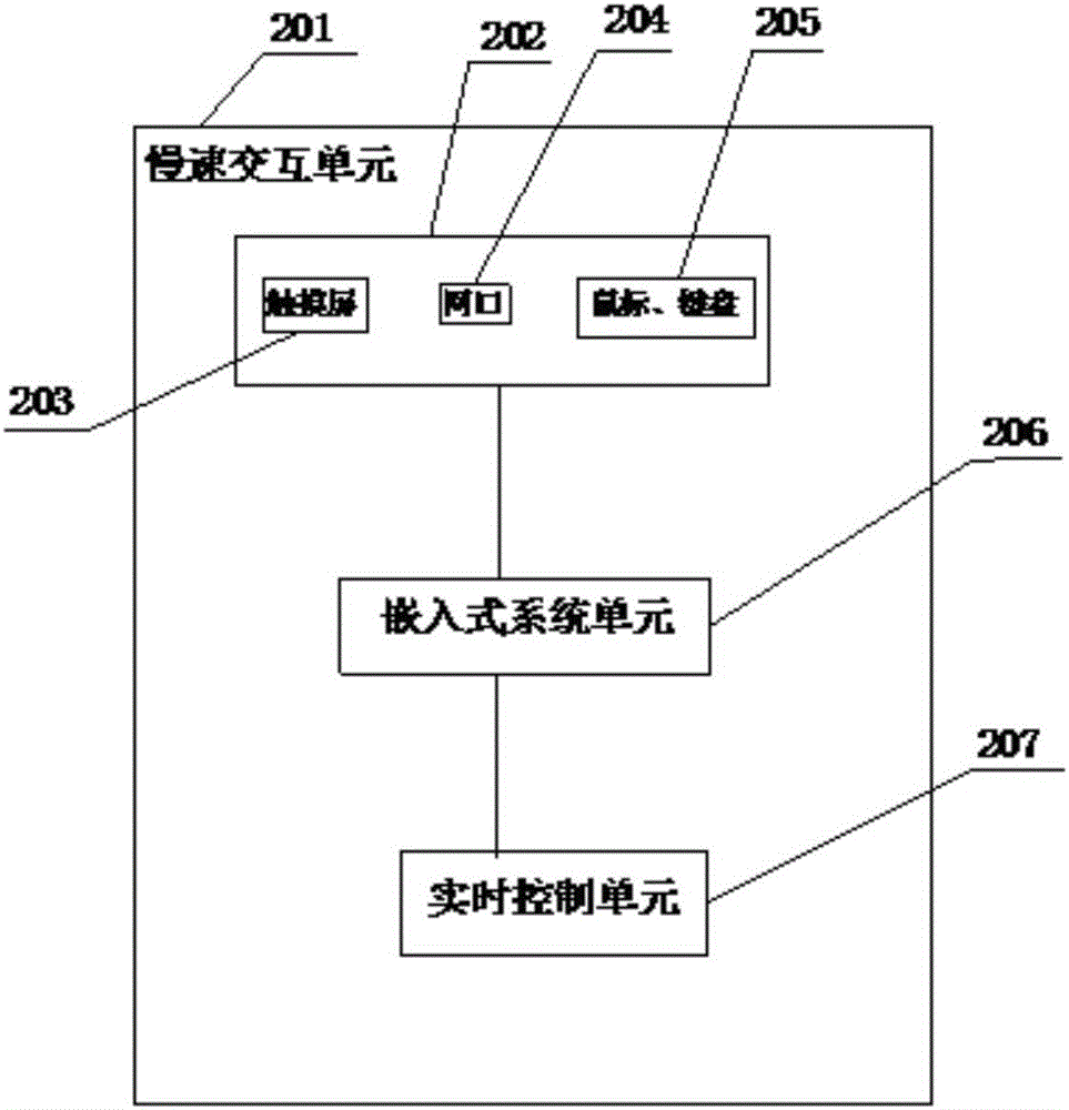
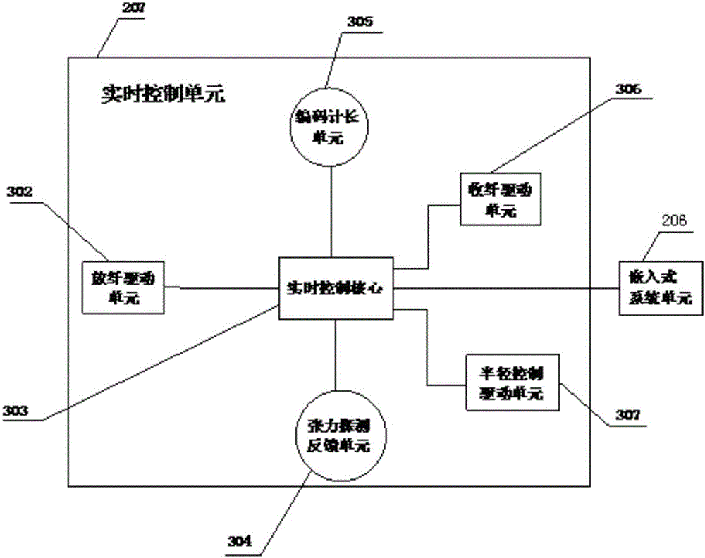
[0035] refer to figure 1 , a fiber winding machine system, including a mechanical structure unit 101 and a slow interaction unit 201, the mechanical structure unit 101 is composed of a fiber pay-off unit 102, a first guiding device 103, a buffer device 105, a length measuring device 106, and a pressure sensor 107 , the second guiding device 108, and the fiber receiving unit 109 are sequentially connected by the optical fiber 104, and the optical fiber reel to ...


PUM


Abstract

The invention discloses a fiber winding system, which comprises a mechanical structure unit and a low-speed interaction unit, and is characterized in that the mechanical structure unit is composed of a fiber releasing unit, a first guiding device, a buffer device, a length metering device, a pressure sensor, a second guiding device and a fiber collecting unit, the slow-speed interaction unit is composed of a man-machine interaction unit, an embedded system unit and a real-time control unit, and the real-time control unit is composed of a fiber release driving unit, a fiber collection driving unit, a radius control driving unit, a code length metering unit, a tension detection feedback unit and a real-time control core. The invention further relates to an automatic control method of a fiber winding machine, which comprises a tension closed-loop control method and a length metering automatic stop control method. The fiber winding system is simple in structure, low in cost and high in fiber winding efficiency, can ensures that optical fiber tension control is enabled to be sable and that system operation is enabled to be steady when the system is in high-speed operation, and can wind optical fiber loops with different radiuses very conveniently at the same time.

Description

【Technical field】 [0001] The invention relates to the field of automatic control of fiber winding machines, in particular to a fiber winding machine system and an automatic control method. 【Background technique】 [0002] At present, there are many types of winding machines used in the field of cable rewinding, but there are not many optical fiber winding equipment used in the field of optical module production. Existing technologies mainly include manual rewinding using molds and automatic control by single-chip microcomputers. There are many deficiencies in manual rewinding, such as low efficiency and inaccurate length calculation. Although the single-chip microcomputer control method can realize automatic control, due to the serial operation mode of the single-chip microcomputer, the real-time performance of the control is greatly reduced, and the fiber tension control is also unstable, which may have a negative impact on the quality of the wound optical fiber ring. The ...

Claims


Application Information

Patent Timeline
Patent Type & Authority Applications(China)
IPC IPC(8): G05B19/042G05D27/02
CPCG05B19/042G05D27/02
Inventor 辜勇陈志曾炼杨宇翔
Owner GUANGXUN SCI & TECH WUHAN
Why Eureka
Try Eureka