Scalable force and electric field transmission electron microscope in situ sample rod

An electron microscope and sample rod technology, applied in circuits, discharge tubes, electrical components, etc., can solve the problems of difficult installation, single function, high price, etc., and achieve the effect of shortening the service life, broadening the research field, and reducing the difficulty of operation.

Inactive Publication Date: 2016-10-26
LANZHOU UNIVERSITY
View PDF5 Cites 12 Cited by
  • Summary
  • Abstract
  • Description
  • Claims
  • Application Information

AI Technical Summary

Problems solved by technology

[0004] At home and abroad, there is no expandable electromechanical two-field transmission electron microscope in-situ sample holder. At present, the commercial in-situ mechanical or electrical transmission electron microscope sample holder has single function and high price, and has the following problems:
However, since the maximum output displacement of the piezoelectric ceramic tube is generally lower than tens of microns, the sample must be placed within a few tens of microns away from the nanoprobe when loading, which increases the difficulty of the experimental operation.
[0006] 2. Existing commercial sample rods, the replacement of the front-end nano-probe is more complicated, and the material manufacturer is limited, so the installation is difficult
[0007] 3. On the basis of ensuring the mechanical loading, the existing sample rods have relatively simple electrical functions, most of which only meet the requirements of single-electrode testing, and the sample rod head and the sample rod are solidified as a whole, which cannot realize the replacement of special samples and the effective expansion of the function of the sample rod

Method used


Image

  • Scalable force and electric field transmission electron microscope in situ sample rod
  • Scalable force and electric field transmission electron microscope in situ sample rod
  • Scalable force and electric field transmission electron microscope in situ sample rod

Examples


Embodiment 1

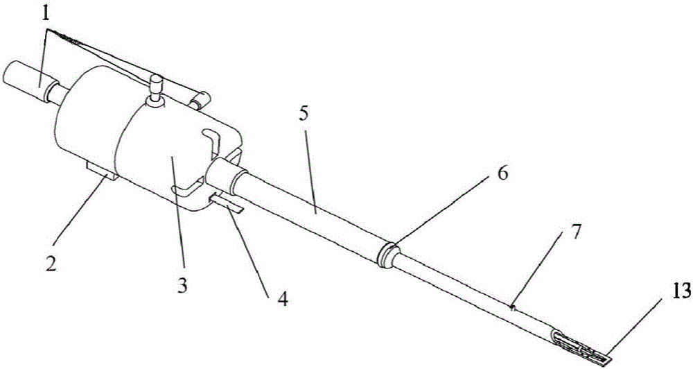
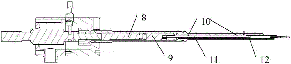
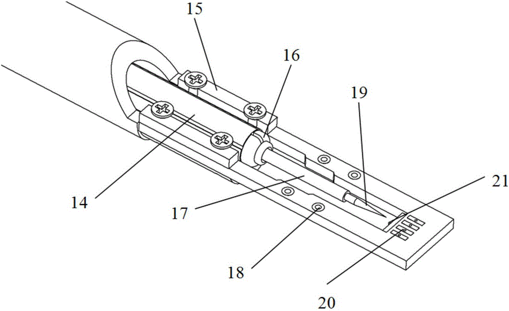
[0029] Example 1, such as Figure 1-3 As shown, the in-situ sample rod of the extensible electromechanical two-field transmission electron microscope includes a coarse adjuster 1, a signal adapter 2, a sample rod housing 5, a coarse adjustment adapter 8, an adapter fixing rod 9, a coaxial ring 10, Transmission rod 11, piezoelectric ceramic holder 12, sample rod head 13, piezoelectric ceramic tube 14, fixed part 15, needle tip holder 16, conductive needle tube 17, conductive electrode 18, nano needle tip 19 and test electrode 20;

[0030] The axial part of the coarse adjuster 1 is mechanically connected coaxially with the sample rod housing 5, and the axial part and the radial part of the coarse adjuster 1 are respectively mechanically connected with the sample rod housing 5 to realize the coaxial fixation of the coarse adjuster. 1 is connected with the coarse adjustment adapter 8 to realize the conversion of the rotational movement and the axial telescopic movement, the coarse...

Embodiment 2

[0033] Example 2, such as figure 1 As shown, on the basis of Example 1, the in-situ sample rod of the expandable force-electric two-field transmission electron microscope also includes a hand handle 3, which is connected to the sample rod shell 5 to realize the movement of the sample rod Use, and can achieve a large range of movement.

Embodiment 3

[0034] Embodiment 3, on the basis of Embodiment 2, the handle 3 is provided with a sensing pin 4, and the sensing pin 4 is used to realize the sensing positioning of the sample rod inserted into the transmission electron microscope.


PUM


Abstract

The invention provides a scalable force and electric field transmission electron microscope in situ sample rod which comprises a coarse adjusting device, a signal adapter, a sample rod shell, a coarse adjustment adapter, a switching fixed rod, a coaxial ring, a transmission rod, a piezoelectric ceramic holder, a sample rod head, a piezoelectric ceramic tube, a fixed part, a needle fixed device, a conductive needle tube, a conductive electrode, a nano tip and a test electrode. Test and the control signal lines are inserted into the signal adapter, the electrical control connection of an external control testing module and the piezoelectric ceramic tube, the nano tip and a sample is realized. After the sample rod is inserted into a transmission electron microscope, the coarse adjusting device is controlled to accurately move the nano tip to the fine adjustment range of the sample, through adjusting the driving signal of the external control testing module, the in situ deformation of the piezoelectric ceramic tube is controlled, thus the nano tip is controlled to accurately move in a nano level in a fine adjustment range, finally the mechanical and optical contact of the nano tip and a testing sample is realized, and a force and electric performance in situ experiment is completed.

Description

technical field [0001] The invention belongs to the field of nanometer material measurement. The invention relates to the research fields of transmission electron microscope accessories and in-situ measurement of nanomaterials, and specifically discloses an expandable electromechanical two-field transmission electron microscope in-situ sample rod. Background technique [0002] With the continuous maturity and development of electron microscope in-situ technology, transmission electron microscope (transmission electron microscope or TEM) no longer only characterizes the structure of materials, but also can realize high-precision nanofabrication and performance testing. Performance (such as force, electricity, heat) changes are linked. [0003] To complete the above functions, a series of in-situ physical property test sample rods must be used. However, due to the limitation of the sample chamber size (millimeter level) of the transmission electron microscope, the difficulty ...

Claims


Application Information

Patent Timeline
Patent Type & Authority Applications(China)
IPC IPC(8): H01J37/20H01J37/26
CPCH01J37/20H01J37/26H01J2237/20278
Inventor 彭勇郑修军夏卫星田悦关超帅胡阳杨保林周保范薛德胜
Owner LANZHOU UNIVERSITY
Why Eureka
Try Eureka