A High-Gain T-Probe-Fed Millimeter-Wave Patch Antenna

A high-gain, wave patch technology, applied in antennas, antenna grounding switch structure connection, devices that make antennas work in different bands at the same time, etc., can solve the problems of strong gas absorption effect, high free space transmission attenuation, etc. Cross-polarization, good radiation characteristics, the effect of increasing the gain

Active Publication Date: 2019-05-14
SOUTH CHINA UNIV OF TECH
View PDF3 Cites 0 Cited by
  • Summary
  • Abstract
  • Description
  • Claims
  • Application Information

AI Technical Summary

Problems solved by technology

5G (the fifth generation) communication is developed on the basis of 4G communication. It is still in the research stage, and it will take a long time before it is officially put into use.
However, since the signal in the 57-64GHz frequency band has high free-space transmission attenuation and strong atmospheric absorption effect, it is necessary to design a high-gain antenna

Method used


Image

  • A High-Gain T-Probe-Fed Millimeter-Wave Patch Antenna
  • A High-Gain T-Probe-Fed Millimeter-Wave Patch Antenna
  • A High-Gain T-Probe-Fed Millimeter-Wave Patch Antenna

Examples


Embodiment 1

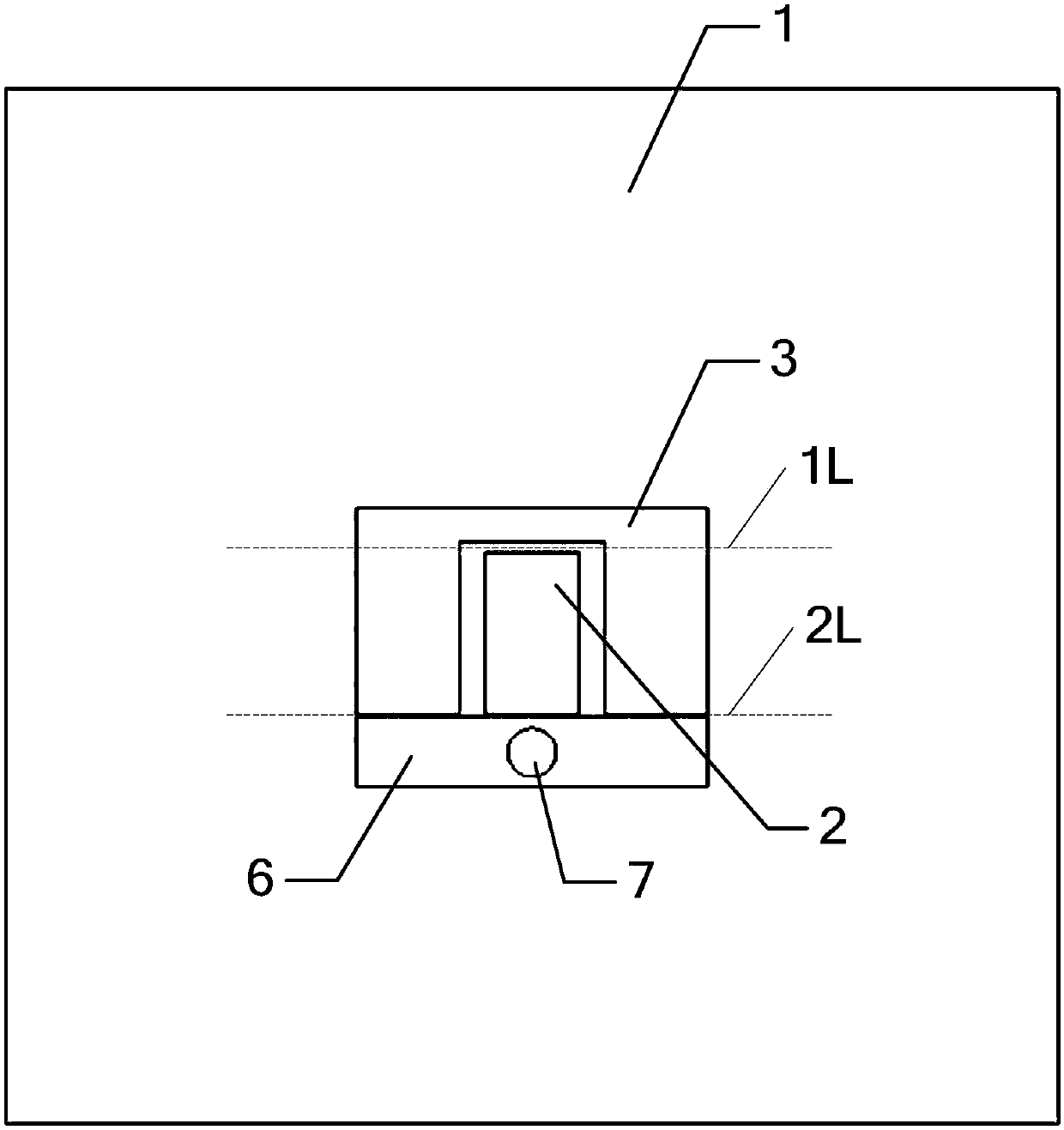
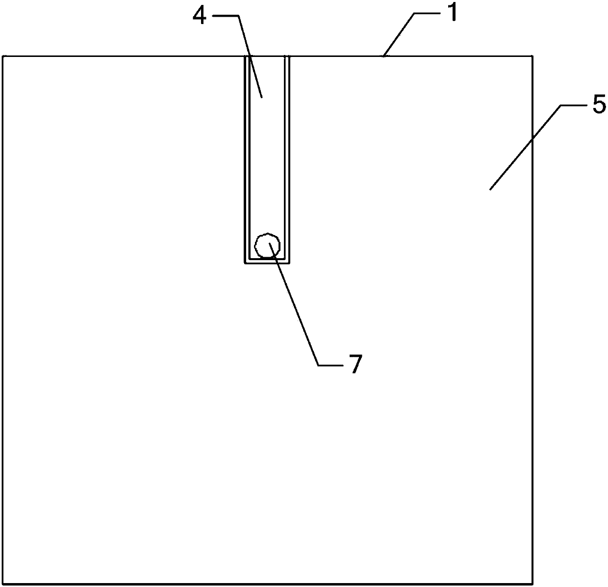
[0031] Such as figure 1 and figure 2 As shown, the millimeter-wave patch antenna of this embodiment includes a first dielectric substrate 1, on which a T-shaped probe, a first radiation patch 2, a second radiation patch 3, a first The coplanar waveguide transmission line 4 and the second coplanar waveguide transmission line 5 .

[0032] The millimeter-wave patch antenna of this embodiment uses a T-shaped probe to feed the first radiating patch 2 and the second radiating patch 3 to generate two resonant modes, in which the first radiating patch 2 generates High-frequency resonance mode, the second radiation patch 3 produces a low-frequency resonance mode, which ensures that the antenna has a wider impedance bandwidth; the T-shaped probe is composed of a horizontal patch 6 and a vertical metal via 7, so The horizontal patch 6, the first radiating patch 2 and the second radiating patch 3 are arranged on the front of the first dielectric substrate 1, and between the horizontal ...

Embodiment 2

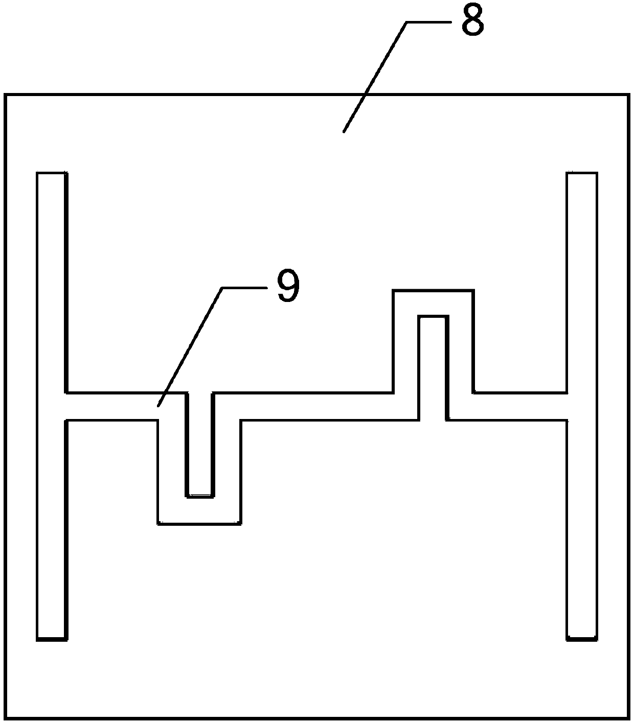
[0035] Such as Figure 1 ~ Figure 4 As shown, the millimeter-wave patch antenna of this embodiment also includes two second dielectric substrates 8, the two second dielectric substrates 8 are symmetrical up and down, and each second dielectric substrate 8 is arranged on the first dielectric substrate 1 The upper end, and one or more ZIM units 9 are loaded on the front side of each second dielectric substrate 8. The following describes the loading of one ZIM unit 9 and three ZIM units 9 on the second dielectric substrate 8:

[0036] 1) When a ZIM unit 9 is loaded on the front of each second dielectric substrate 8, such as image 3 As shown, the ZIM unit 9 includes a first vertical section, a second vertical section and a bent section, the first vertical section and the second vertical section are left and right symmetrical, and the two ends of the bent section are respectively Connected with the first vertical section and the second vertical section, the bent section consists ...

Embodiment 3

[0041] In the millimeter-wave patch antenna of this embodiment, the dielectric constant of the first dielectric substrate 1 is 2.2, and the dielectric constant of the two second dielectric substrates 2 is 5.9. The entire millimeter-wave patch antenna uses a T-shaped probe to The radiating patch (the second radiating patch 3) and the small radiating patch (the first radiating patch 2) are fed to enable the antenna to achieve a wide impedance bandwidth. The T-shaped probe consists of a horizontal patch 6 and a vertical metal The horizontal patch 6 is a rectangular copper sheet, the center of the vertical metal via hole 7 is located at the geometric center of the rectangular copper sheet, and the horizontal patch 6, the first radiation patch 2 and the second radiation patch 3 is printed on the front of the first dielectric substrate 1; the entire millimeter-wave patch antenna is fed through the coplanar waveguide, and the first coplanar waveguide transmission line 4 and the second...


PUM


Abstract

The invention discloses a high gain T-shaped probe feed millimeter wave patch antenna. The high gain T-shaped probe feed millimeter wave patch antenna comprises a first medium substrate, wherein the first medium substrate is provided with a T-shaped probe, a first radiation patch, a second radiation patch, a first coplanar waveguide transmission wire and a second coplanar waveguide transmission wire, the T-shaped probe comprises a horizontal patch and a vertical metal through hole, the horizontal patch, the first radiation patch and the second radiation patch are arranged on a front surface of the first medium substrate, distances between the horizontal patch and the first radiation patch and the second radiation patch are identical, the first coplanar waveguide transmission wire and the second coplanar waveguide transmission wire are arranged on a back surface of the first medium substrate, and the vertical metal through hole is arranged at a center of the horizontal patch and sequentially penetrates through the horizontal patch, the first medium substrate and the first coplanar waveguide transmission wire. The high gain T-shaped probe feed millimeter wave patch antenna is advantaged in that an excellent radiation directional diagram is realized, a stable and relatively high gain is realized in the whole work frequency band, and simple design, small volume, low cost and good characteristics are realized.

Description

technical field [0001] The invention relates to a millimeter-wave patch antenna, in particular to a high-gain T-shaped probe-fed millimeter-wave patch antenna, which belongs to the technical field of wireless mobile communication. Background technique [0002] With the development of mobile communication technology, mankind has entered the era of 4G (the 4th generation) as a whole, and 4G communication has laid a solid foundation for the further development of communication technology. Since the Federal Communications Commission (FCC) of the United States opened the 7GHz frequency band of 57-64GHz as a free frequency band, people have done a lot of work around the 60-GHz frequency band. 5G (the fifth generation) communication is developed on the basis of 4G communication. It is still in the research stage, and it will take a long time before it is officially put into use. Since the signals in the millimeter wave frequency band are very suitable for high-speed data transmiss...

Claims


Application Information

Patent Timeline
Patent Type & Authority Patents(China)
IPC IPC(8): H01Q1/38H01Q1/50H01Q15/00H01Q5/10H01Q5/55
CPCH01Q1/38H01Q1/50H01Q5/10H01Q5/55H01Q15/0086
Inventor 甘正涂治红姚越
Owner SOUTH CHINA UNIV OF TECH
Why Eureka
Try Eureka