Electromechanical rotational damper with tension and compression stop

A technology of rotating shock absorbers and shock absorbers, applied in non-rotating vibration suppression, springs/shock absorbers, mechanical equipment, etc.

Active Publication Date: 2016-10-26
AUDI AG
View PDF8 Cites 3 Cited by
  • Summary
  • Abstract
  • Description
  • Claims
  • Application Information

AI Technical Summary

Problems solved by technology

But this type of braking device does not have the necessary reliability in connection with the rotary shock absorber for the suspension of motor wheels

Method used


Image

  • Electromechanical rotational damper with tension and compression stop
  • Electromechanical rotational damper with tension and compression stop
  • Electromechanical rotational damper with tension and compression stop

Examples


Embodiment Construction

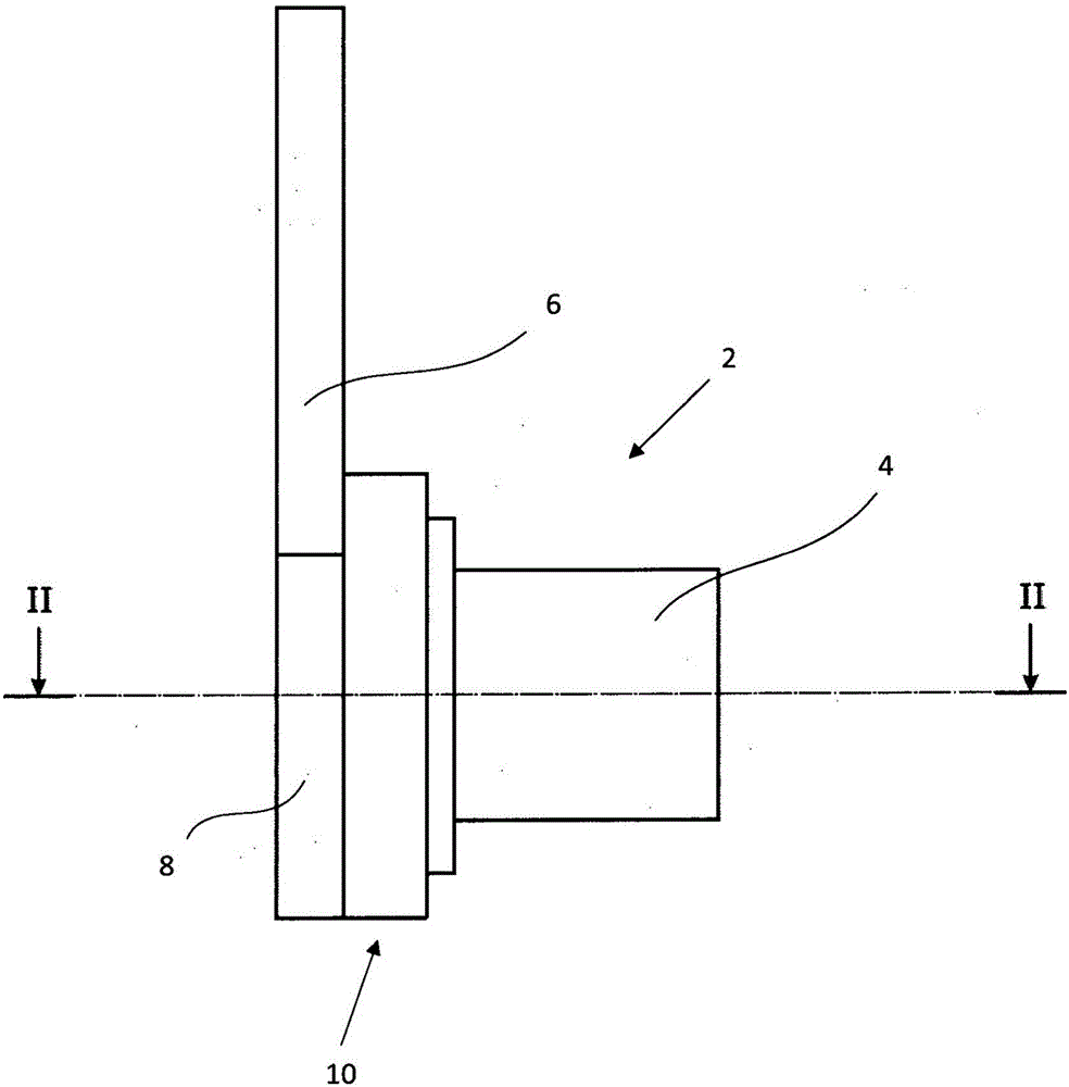
[0023] figure 1 A side view of a torsional vibration damper 2 is shown, which has a damper housing 4 fastened to a mass, the wheel suspension, by fasteners (not shown) or on the vehicle body. The articulated rod 6 is mounted pivotably relative to the shock absorber housing 4 and is connected to a second mass, ie the vehicle body or the wheel suspension. The articulated rod 6 is connected to a housing cover 8 , which is rotatably mounted on the shock absorber housing 4 . A harmonic drive 10 is arranged between the damper housing 4 and the housing cover 8 .

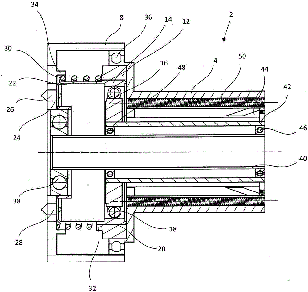
[0024] figure 2 showing along figure 1 The II-II line in the section cuts the sectional view of the rotary vibration absorber. The torsional vibration damper 2 here comprises a harmonic drive comprising a rigid unit 12 with internal toothing connected to the damper housing 4 and a rigid unit 12 with external toothing connected to the housing cover 8 . The connected flexible unit 14 is described below. The two units ...


PUM


Abstract

A rotational damper (2) having a damper housing (4) which surrounds an electromagnetic damper motor and is fastened via a fastening part to a first mass, and having a coupling lever (6) which is mounted pivotably with respect to the damper housing (4) and is connected to a second mass, a strain wave gear mechanism (10) for vibration damping which has a rigid unit (12) which has an internal toothing system and is connected to the damper housing (4), and a flexible unit (14) which has an external toothing system and is connected to the fastening part. The two units of the strain wave gear mechanism (10) are coupled to one another in a positively locking manner via the toothing systems in order to transmit and / or convert a rotational movement. A wave generator is mounted rotatably in the flexible unit (14), upon the rotation of which wave generator the flexible unit is deformed. A wrap spring (30) is arranged in an operative connection with the flexible unit (14), which wrap spring (30) is connected on one side to the coupling lever (6) and on the other side to the fastening part, in each case fixedly so as to rotate with it, wherein the wrap spring (30) is designed in order to lock the strain wave gear mechanism (10) by way of deformation of the flexible unit (14) in the case of predefined pivoting of the coupling lever (6) with respect to the fastening part.

Description

technical field [0001] The invention relates to a rotary vibration absorber, which has: a shock absorber housing, which surrounds an electromagnetic damping motor and is fastened on a first mass body by a fastener; A rod, which is connected to the second mass body and is pivotably supported relative to the shock absorber housing; a harmonic drive for vibration damping, which comprises a vibration damper with internal toothing A housing-connected rigid unit and a fastening-connected flexible unit with external toothing, wherein the two units of the harmonic drive are positively coupled to each other via the toothing for the transmission and / or conversion of rotational movements and an oval wave generator rotatably supported in the flexible unit, the flexible unit being deformed when the wave generator rotates. Background technique [0002] An electric damper of the type indicated at the outset is known from WO 2011 / 042085 A1 for damping the relative movement between a first ...

Claims


Application Information

Patent Timeline
Patent Type & Authority Applications(China)
IPC IPC(8): F16F15/03B60G13/14
CPCB60G13/14F16F15/035B60G2300/60B60G2202/22B60G2202/422B60G2204/4191B60G2204/45B60G2206/41B60G15/02B60G2202/30B60G2204/419F16F15/022F16F15/03
Inventor M·威莱姆斯
Owner AUDI AG
Why Eureka
Try Eureka