Vein puncture needle

A technique of venipuncture and needle, which is applied to needles, instruments introduced into the body, etc., can solve the problems of indwelling needles that cannot quickly display blood return, judge whether it has been pierced, pierced the vein, etc.

Active Publication Date: 2016-11-02
BEIJING WANSHENG RENHE TECH
View PDF11 Cites 8 Cited by
  • Summary
  • Abstract
  • Description
  • Claims
  • Application Information

AI Technical Summary

Problems solved by technology

[0007] The purpose of the present invention is to provide a venipuncture needle. First, it solves the technical problem that the existing indwelling needle cannot quickly display blood return and judge whether it has penetrated into the patient's venous blood vessel; The method of parallel displacement controls the risk of puncturing the vein caused by the retraction of the tip of the needle into the catheter; thirdly, the components that assist in quickly displaying ve

Method used


Image

  • Vein puncture needle
  • Vein puncture needle
  • Vein puncture needle

Examples


Embodiment 1

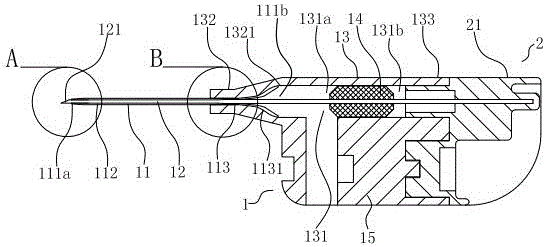
[0071] Such as Figure 1-7 As shown, a venipuncture needle includes a catheter 11, a needle head 12, a needle seat 13, an isolation plug 14, a needle handle 15, and a needle withdrawal assembly 2. The catheter 11 is made of polyurethane material or silicone material, and is hollow inside as a whole. The inside of the catheter lumen 111 is a catheter lumen 111. One end of the catheter lumen 111 is opened as a catheter liquid outlet hole 111a, and the other end is opened as a catheter liquid inlet hole 111b. One end of the liquid inlet hole 111b is a catheter connection part 113; the needle 12 is made of stainless steel, and the needle 12 is also a hollow tube with a needle cavity 123, a tip part 121, and a needle body part 122. The needle body The part 122 is accommodated in the catheter lumen 111, and its tip part 121 protrudes from the catheter outlet hole 111a of the catheter lumen 111; the needle hub 13 is injection molded with propionate material or acrylonitrile-styrene-b...

Embodiment 2

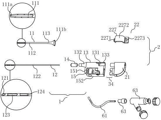
[0075] Such as Figure 8As shown, the manipulation component 22 is a capsule 221 located on the first surface 151 of the needle handle. The capsule 221 is made of silicone material. One method is that the sheet material of the capsule 221 is bonded to the first surface of the needle shaft. 151, the two together form a capsule lumen 221a. Another method is that the bag-shaped capsule 221 is bonded to the first surface 151 of the needle handle, and the bag-shaped capsule 221 has a capsule lumen 221a. The inner cavity of the capsule 221a can be preset with fluid, and the fluid is gas or liquid. The inner cavity of the capsule 221a is connected with the needle withdrawal cavity 131b, and the capsule body 221 on the first surface 151 of the needle handle is pressed to close the inner cavity of the capsule cavity 221a. The fluid is filled into the needle withdrawal chamber 131b, and the driving displacement member 21 drives the needle 12 to move from the initial state 31 to the firs...

Embodiment 3

[0078] Such as Figure 8 , 10 As shown, in order to ensure the gentleness of the needle withdrawal of the displacement part 21, a piston 211 is connected to the displacement part 21. The piston 211 is made of silica gel material, is located inside the needle withdrawal chamber 131b, and is connected with the needle head 12. The piston 211 The outer wall is in movable and smooth contact with the inner wall of the needle withdrawal cavity 131b. When the human finger presses the capsule 221 on the first surface 151 of the needle handle to fill the fluid in the capsule cavity 221a into the needle withdrawal cavity 131b, the piston 211 can be driven to The displacement in the direction of the rear end 133 of the needle base drives the displacement of the needle 12 from the initial state 31 to the first state 32 . The gap between the outer wall of the piston 211 and the inner wall of the needle withdrawal chamber 131b is easier to control during the manufacturing process, and the p...


PUM


Abstract

The invention provides a vein puncture needle which comprises a conduit, a needle probe, a needle holder, a needle handle, and a needle retreating component on the needle handle. The needle retreating component utilizes an operation and control component to control a displacement component to make the needle probe displace in steps and to conveniently allow a second propulsion conduit to enter the proper position of a patient's vein, therefore, raising the success rate of vein puncturing of the puncture needle. The needle retreating component provided by the vein puncture needle has a simple structure and the use of functions is made in a proper order, which not only raises the success rate of vein puncturing of the puncture needle but also effectively protects medical workers from being accidentally injured after the use of the puncture needle.

Description

technical field [0001] The invention relates to a venipuncture needle, in particular to an indwelling needle used for human intravenous infusion and hemodialysis, and belongs to the technical field of medical equipment production. Background technique [0002] An intravenous indwelling needle is a medical device used for treatment such as intravenous infusion and hemodialysis. The existing intravenous indwelling needle has a flexible catheter and a metal needle inside the catheter. The tip of the needle is exposed outside the indwelling part of the catheter. When in use, the tip of the needle passes through the patient's skin and is inserted into the target vein, so that part of the indwelling part of the catheter and the front end of the needle enter the target vein, and the catheter and the needle continue to enter the vein for a second time until the catheter reaches a suitable position in the vein, and the needle is removed from the catheter out. In some cases, when the...

Claims


Application Information

Patent Timeline
IPC IPC(8): A61M5/158
CPCA61M5/158A61M2005/1588
Inventor 董东生周慷李娜
Owner BEIJING WANSHENG RENHE TECH
Why Eureka
Try Eureka