A Leakage Detection System for Underground Diaphragm Wall in Soft Soil Area
What is Al technical title?
Al technical title is built by PatSnap Al team. It summarizes the technical point description of the patent document.
An underground diaphragm wall and detection system technology, which is applied in the test of infrastructure, construction, infrastructure engineering, etc., can solve the problems of complex construction, low accuracy of measurement results, and difficulty in measuring leakage points of underground diaphragm walls. The effect of shortening the construction period, high accuracy and convenient operation
Active Publication Date: 2018-07-17
ZHEJIANG UNIVERSITY OF SCIENCE AND TECHNOLOGY
View PDF4 Cites 0 Cited by
Summary
Abstract
Description
Claims
Application Information
AI Technical Summary
This helps you quickly interpret patents by identifying the three key elements:
Problems solved by technology
Method used
Benefits of technology
Problems solved by technology
[0012] In order to solve the deficiencies of complex construction, difficult measurement, and low accuracy of measurement results in the detection of leakage points of underground diaphragm walls, the invention provides a detection device for leakage points of underground diaphragm walls in soft soil areas, which effectively solves the problems of complex construction, measurement Difficulty, low accuracy of measurement results, etc., and at the same time, it can accurately measure the specific location of the leakage point
Method used
Image
Click on the blue label to locate the original text in one second.
Reading with bidirectional positioning of images and text.
Examples
Embodiment Construction
[0066] In order to make the technical problems, technical solutions and beneficial effects solved by the present invention clearer, the present invention will be further described in detail below in conjunction with the accompanying drawings.
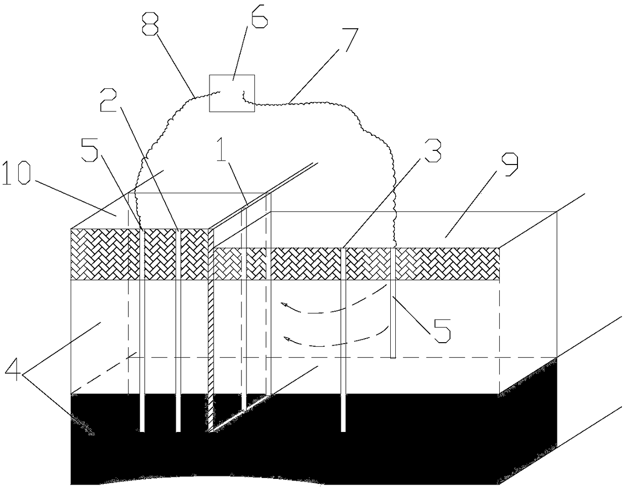
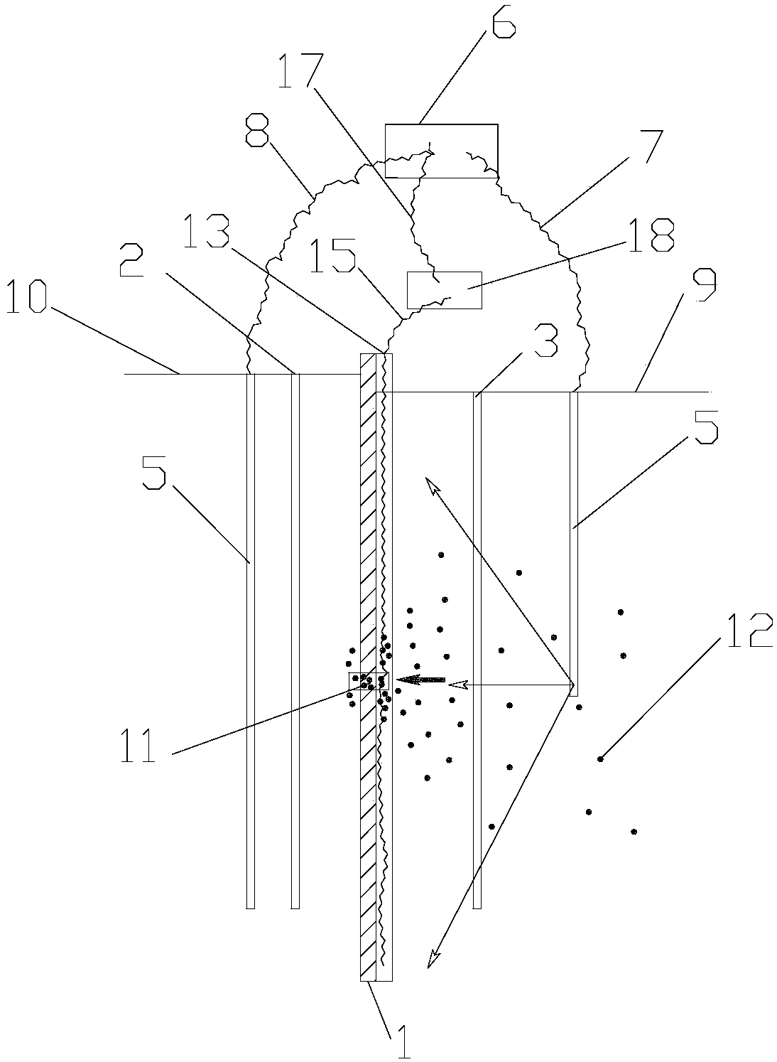
[0067] A leak detection device for underground diaphragm walls in soft soil areas, comprising 13 a sampling device, 131 a sliding cover, 132 a corbel, 133 an open cylinder, 134 gauze, 135 a partition, and 136 a round hole. The three-dimensional diagram of the device is shown in the appendix image 3 .
[0068] refer to figure 1 , figure 2 and image 3 , an underground diaphragm wall leakage detection device in a soft soil area, the method includes the following steps:
[0069] 1) Carry out a pumping test on the inner side of the foundation pit, observe the water level change of the observation well 2 outside the foundation pit, if the water level of the observation well 2 does not change greatly, then there is no leakage point 11 i...
PUM
Abstract
The invention discloses a soft soil area underground continuous wall leakage detecting system, solves such defects as complex construction, difficult measurement and lower accuracy of measured results, and measures specific positions of leakage points more accurately. The transport process of underground ions and the gathering process of the underground ions are observed in real time, so that the specific positions of the leakage points can be obtained more quickly and accurately. The soft soil area underground continuous wall leakage detecting system relates to a underground continuous wall, an observation well, a precipitation well, a soft soil layer, an aluminum electrode, an electrifying device, an electrifying device positive pole, an electrifying device negative pole, an in-pit ground, an out-pit ground, the leakage points, aluminum ions, a sampling device, a slide cover, a bracket, an opening cylinder, a gauze, a separation plate, a round hole, a sensor, a circuit, a circuit fixator, a circuit negative pole and an acquiring system. The underground continuous wall is not limited by thickness and depth. The observation well is used for observing change of an underground water level on the outer side of a foundation pit; the gap and the depth of the observation well are determined according to actual engineering; and the observation well also can serve as a foundation pit outer side precipitation well. The precipitation well is a foundation pit inner side precipitation well, and can be used for observing a underground water level on the inner side of the foundation pit. The soft soil layer is a soil layer suitable for an electroosmosis method.
Description
technical field [0001] The invention relates to an underground continuous wall leakage detection system, which is suitable for the leakage detection of the underground continuous wall in foundation pit enclosure and belongs to the technical field of building construction. Background technique [0002] During the construction of the underground diaphragm wall, in order to prevent accidents caused by the leakage of the underground diaphragm wall, the leakage of the underground diaphragm wall is often detected before construction to ensure the safety of the foundation pit. In the foundation pit enclosure design, the underground diaphragm wall has the effect of waterproofing, but there are still more than 70% of foundation pit engineering accidents caused directly or indirectly by water damage. The surrounding environment is safe, causing loss of people's life and property. Since the underground concrete diaphragm wall is deeply buried in the soil, with a depth of more than ten...
Claims
Application Information
Patent Timeline
Application Date:The date an application was filed.
Publication Date:The date a patent or application was officially published.
First Publication Date:The earliest publication date of a patent with the same application number.
Issue Date:Publication date of the patent grant document.
PCT Entry Date:The Entry date of PCT National Phase.
Estimated Expiry Date:The statutory expiry date of a patent right according to the Patent Law, and it is the longest term of protection that the patent right can achieve without the termination of the patent right due to other reasons(Term extension factor has been taken into account ).
Invalid Date:Actual expiry date is based on effective date or publication date of legal transaction data of invalid patent.
Patent Type & Authority Patents(China)
IPC IPC(8): E02D33/00
CPCE02D33/00
Inventor 罗战友李超邹宝平陶燕丽
Owner ZHEJIANG UNIVERSITY OF SCIENCE AND TECHNOLOGY