

Turbine disc cavity structure with closely-sealing and cooling guide plate
A technology of deflectors and turbine discs, applied in the direction of supporting components of blades, preventing leakage, engine components, etc., can solve problems such as deterioration of rotor cooling, poor cooling effect, gas intrusion, etc., to avoid vibration and scraping risks, cooling And the sealing is reliable, the effect of eliminating the flow dead angle
- Summary
- Abstract
- Description
- Claims
- Application Information
AI Technical Summary
Problems solved by technology
Method used
Image


Examples
Embodiment Construction
[0021] In order to make the purpose, technical solutions and advantages of the present invention clearer, the present invention will be further described in detail below in conjunction with the examples. The following examples are explanations of the present invention and the present invention is not limited to the following examples.
[0022] It should be noted that implementations not shown or described in the accompanying drawings are forms known to those of ordinary skill in the art. In addition, the directional terms mentioned in the following embodiments, such as "upper", "lower", "front", "backward", "left", "right", "top", "bottom", etc., are only for reference The orientation of the graph. Accordingly, the directional terms are used to illustrate and not to limit the invention.
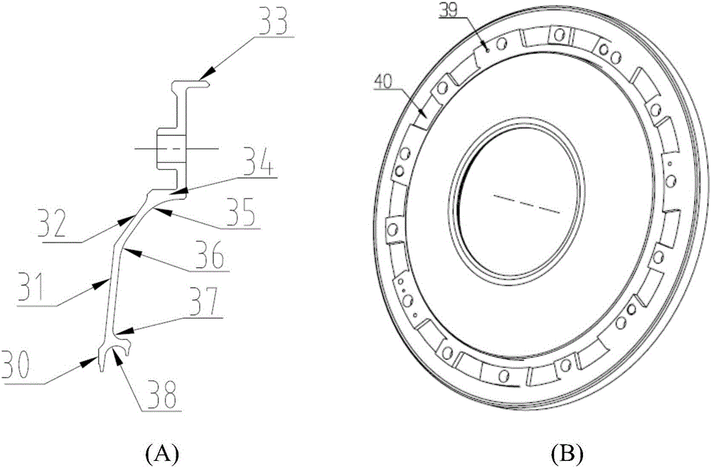
[0023] figure 1 , 2 It is the situation when a typical turbofan engine adopts the turbine disc cavity structure with sealing and cooling deflectors of the present invention. The turbine di...
PUM
| Property | Measurement | Unit |
|---|---|---|
| Tooth spacing | aaaaa | aaaaa |
Abstract
Description
Claims
Application Information