Spline shaft for rotor and stator separation technology of parallel-connection hydrodynamic retarder

A hydraulic retarder, rotor stator technology, applied in the direction of shaft, shaft and bearing, mechanical equipment, etc., to achieve the effect of clear function, flexible adjustment space, and large transmission torque

Inactive Publication Date: 2016-11-09
NINGBO HUASHENG AUTOMOBILE PARTS
View PDF0 Cites 0 Cited by
  • Summary
  • Abstract
  • Description
  • Claims
  • Application Information

AI Technical Summary

Problems solved by technology

[0003] The purpose of the present invention is to provide a spline shaft used for the rotor-stator separation technology of the parallel hydraulic retarder, which overcomes the air loss force generated between the rotor and the stator when the existing retarder is not working, and avoids the air loss. Damage to the car caused unnecessary fuel consumption

Method used


Image

  • Spline shaft for rotor and stator separation technology of parallel-connection hydrodynamic retarder
  • Spline shaft for rotor and stator separation technology of parallel-connection hydrodynamic retarder

Examples


Embodiment 1

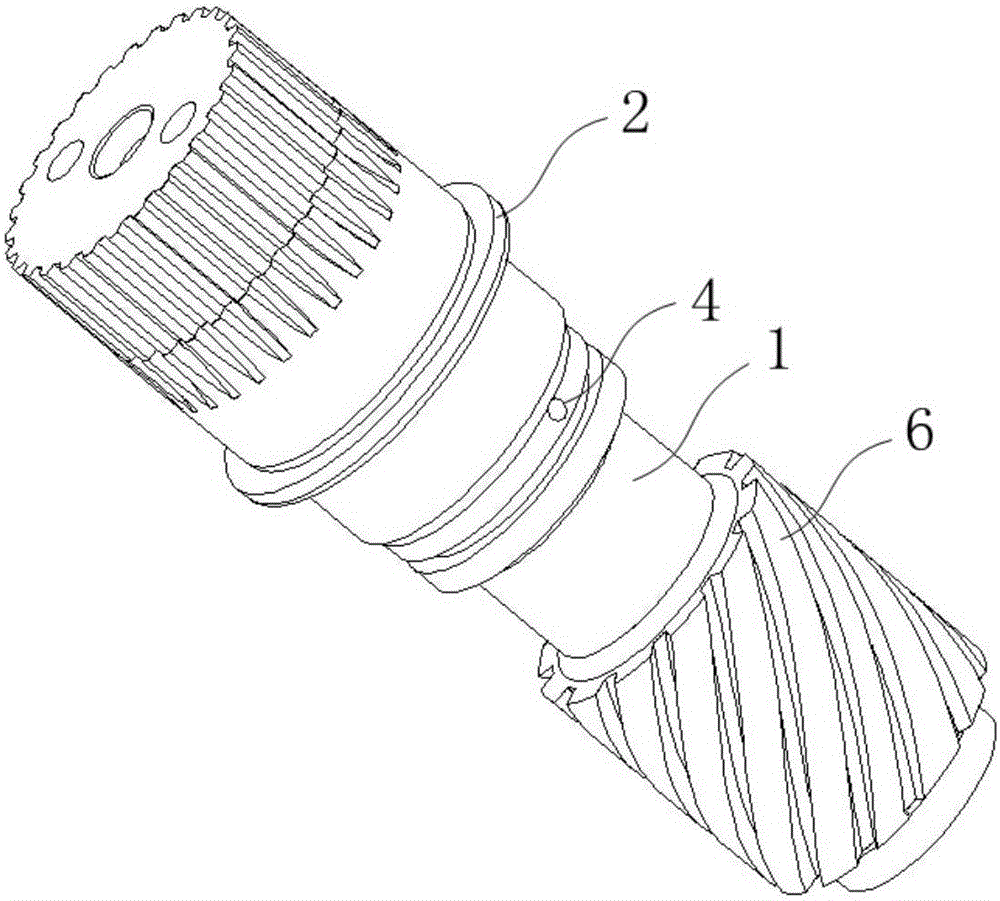
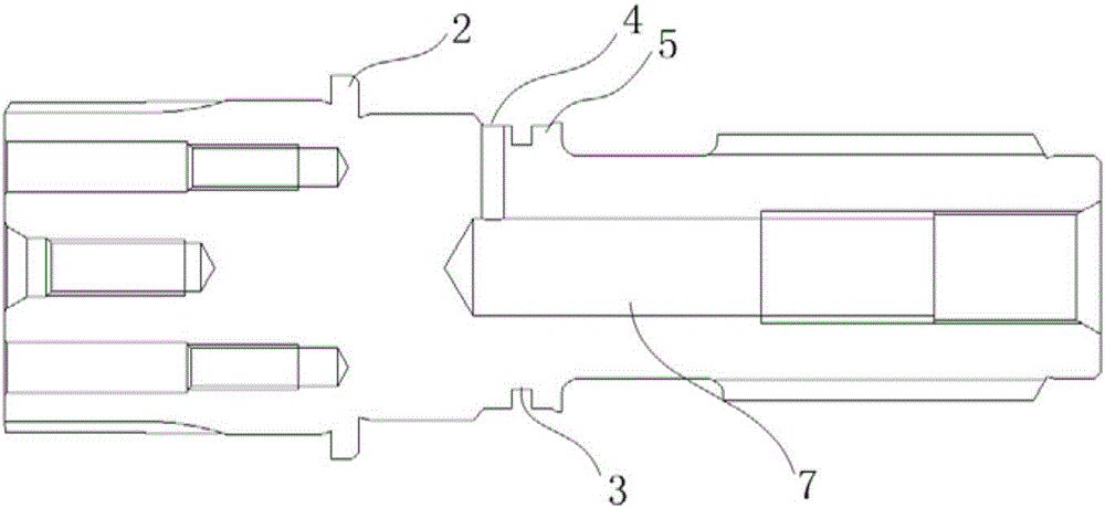
[0017] Such as figure 1 , 2 As shown, the present invention discloses a spline shaft used for rotor-stator separation technology of a parallel hydraulic retarder, including a spline main shaft 1, a limit ring 2, a rotor impeller limit platform 5, a spline main shaft 1 and two The ends are the spline end and the multi-thread end respectively, and the limit ring 2 and the rotor impeller limit platform 5 are arranged respectively from the spline end to the multi-thread end, and an oil seal is set between the limit ring 2 and the rotor impeller limit platform 5 Ring groove 3 and oil cavity through hole 4, the central axis of spline main shaft 1 is provided with threaded hole 7 from multi-start thread end to spline end, and spline main shaft 1 is provided with several multi-start threads 6 away from spline end.

[0018] The multi-start thread 6 has a reverse helical structure, and the number of multi-start threads 6 is 11, wherein the helix angle is 35.52°, the modulus is 3, and t...


PUM


Abstract

The invention relates to the field of mechanical design, and discloses a spline shaft for the rotor and stator separation technology of a parallel-connection hydrodynamic retarder. The spline shaft comprises a spline main shaft, a limiting ring and a rotor impeller limiting table. By means of structure optimization design, multiple sets of multi-step threads are formed at one end of the spline main shaft; by means of repeated test modification, the design parameters of the multi-step threads are optimized, the strength of a designed screw structure is high, transmission torque is large, and a rotor and a stator are close to each other when working and are easy to separate when not working. The reasonably-designed spline shaft is clear in structure, and all portions are clear in function; and structural design has certain flexible adjustment space, the fine adjustment equipment of equipment can be met, and machining and forming are easy.

Description

technical field [0001] The invention relates to the field of mechanical design, in particular to a spline shaft used for the rotor-stator separation technology of a parallel hydraulic retarder. Background technique [0002] Mechanical devices typically transmit torque through keyed or splined connections. There are two types of splines: rectangular splines and involute splines. When the transmission load is large and the centering accuracy is high, the involute spline connection should be used. When the involute spline connection is under load, there is a radial force on the teeth, which can act as an automatic centering, so that the force on each tooth is even, and because the tooth groove is shallow, the stress concentration at the root of the tooth is small, and the weakening of the shaft and the hub Small, so it has the characteristics of high strength and long life. It is widely used in aviation, aerospace, automobile, shipbuilding, engineering machinery, heavy machin...

Claims


Application Information

Patent Timeline
Patent Type & Authority Applications(China)
IPC IPC(8): F16C3/02
CPCF16C3/02
Inventor 袁可定马航魏少辉
Owner NINGBO HUASHENG AUTOMOBILE PARTS
Why Eureka
Try Eureka