Methanol or light hydrocarbon fuel burners

A burner and methanol technology, applied in the direction of liquid fuel burners, burners, combustion methods, etc., can solve the problems of complete combustion difficulties, increased pollution from emissions, and high investment costs, so as to improve combustion efficiency and combustion calorific value, and reduce production The effect of energy consumption and simple operation process

Active Publication Date: 2018-02-09
浙江佑驰能源科技有限公司
View PDF5 Cites 2 Cited by
  • Summary
  • Abstract
  • Description
  • Claims
  • Application Information

AI Technical Summary

Problems solved by technology

[0002] Methanol or light hydrocarbon fuel is vaporized and burned, which can output heat to drive gas turbines or other equipment to work, or directly output heat. The methanol-hydrogen mixed gas auxiliary combustion method, the main fuel is liquid methanol or light hydrocarbon fuel, if there is no gasification , using ordinary nozzles to spray liquid methanol into atomized combustion, there will be incomplete combustion, low thermal efficiency, and increased pollution when discharged
Because the droplet size of the atomized liquid sprayed by ordinary nozzles is still too large, because these droplets have limited contact with the oxygen in the surrounding air, it is difficult to completely burn in a short time
In the existing technology, it is necessary to build a dedicated gasification station, and the investment cost is high. In addition, due to the low calorific value of methanol combustion itself, without the combustion support of hydrogen, the combustion chain reaction cannot be generated, the calorific value cannot be increased, and the ideal energy saving cannot be achieved. Effect

Method used


Image

  • Methanol or light hydrocarbon fuel burners
  • Methanol or light hydrocarbon fuel burners

Examples


Embodiment Construction

[0041] Now in conjunction with accompanying drawing, the present invention will be further described:

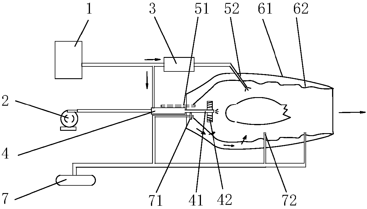
[0042] As shown in the figure, a methanol or light hydrocarbon fuel burner is characterized in that it includes:

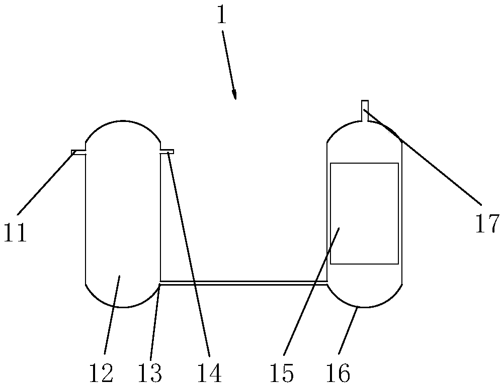
[0043] Hydrogen mixed gas generator 1, the input port is connected with methanol and water vapor;

[0044] Fuel pump 2, the input port is connected to methanol or light hydrocarbon fuel;

[0045] The gasification chamber 4, the input port is connected to the output port of the fuel pump 2 and the output port of the hydrogen mixture generator 1, and the output port is connected to the nozzle 41;

[0046] The temperature swing pressure swing adsorption device 3, the input port is connected to the output port of the hydrogen mixture generator 1;

[0047] In the combustion chamber, the first input port is connected to the nozzle 41 of the gasification chamber 4 , the second input port is connected to the output port of the temperature swing pressure swing adsorpti...


PUM


Abstract

The invention discloses a methanol or light hydrocarbon fuel combustor which comprises a hydrogen mixture generator, a fuel pump, a gasification chamber, a variable-temperature variable-pressure adsorption device and a combustion chamber, wherein an input opening of the hydrogen mixture generator is connected to methanol and water vapor; the input opening of the fuel pump is connected to methanol or light hydrocarbon fuel; the input opening of the gasification chamber is connected to an output opening of the fuel pump and an output opening of the hydrogen mixture generator, and an output opening of the gasification chamber is connected to a nozzle; the input opening of the variable-temperature variable-pressure adsorption device is connected to the output opening of the hydrogen mixture generator and the variable-temperature variable-pressure adsorption device is used for adsorbing CO2 to improve the purity of hydrogen and is prior art; a first input opening of the combustion chamber is connected to the nozzle of the gasification chamber, a second input opening of the combustion chamber is connected to the output opening of the variable-temperature variable-pressure adsorption device, and a third input opening of the combustion chamber is connected to a compressed air pump; the position of the second input opening is a housing corresponding to the center of the combustion chamber; and the position of the second input opening is a position adjacent to the first input opening of the combustion chamber and is parallel to the spraying direction of the nozzle. The methanol or light hydrocarbon fuel combustor has the benefits as follows: more sufficient combustion is achieved, high energy is generated, the exhaust emission is reduced and the environment friendliness is realized.

Description

technical field [0001] The invention relates to a methanol or light hydrocarbon fuel burner which can provide thermal energy. Background technique [0002] Methanol or light hydrocarbon fuel is vaporized and burned, which can output heat to drive gas turbines or other equipment to work, or directly output heat. The methanol-hydrogen mixed gas auxiliary combustion method, the main fuel is liquid methanol or light hydrocarbon fuel, if there is no gasification , using ordinary nozzles to spray liquid methanol into atomized combustion, there will be incomplete combustion, low thermal efficiency, and increased pollution when discharged. Because the droplet size of the atomized liquid sprayed by ordinary nozzles is still too large, and because these droplets have limited contact with the oxygen in the surrounding air, it is difficult to burn completely in a short time. In the existing technology, it is necessary to build a dedicated gasification station, and the investment cost i...

Claims


Application Information

Patent Timeline
Patent Type & Authority Patents(China)
IPC IPC(8): F23D11/24F23D11/38F23D11/40F23D11/36F23D11/10
CPCF23D11/101F23D11/24F23D11/36F23D11/38F23D11/40F23D2202/00
Inventor 陶哲瀚朱伟锋陶永春
Owner 浙江佑驰能源科技有限公司
Why Eureka
Try Eureka