Atomizing combustor for treating industrial hazardous waste liquid

A burner and dangerous technology, applied in the direction of burner, combustion method, combustion type, etc., can solve the problems of excessive discharge of harmful substances, incomplete combustion, air pollution, etc., and achieve the effects of reducing hazards, facilitating operation, and protecting the environment

Inactive Publication Date: 2016-11-09
王海升
View PDF9 Cites 7 Cited by
  • Summary
  • Abstract
  • Description
  • Claims
  • Application Information

AI Technical Summary

Problems solved by technology

[0002] Hazardous industrial waste has increasingly become a major factor threatening our country's environment, especially hazardous waste liquids are dumped indiscriminately, polluting air and water sources. The incineration of waste liquids is an effective way to deal with industrial hazardous waste liquids. The secondary pollution is low. The liquid burning burners on the market can only use low-viscosity, clean, and stable fuels. The structure of the atomizing nozzle is complex, and it is particularly easy to block. Disposal and incineration of industrial hazardous waste liquid with a certain calorific value. Industrial hazardous waste liquid generally has complex components and contains certain particles of impurities, and has a high viscosity. Units that dispose of industrial hazardous waste liquid cannot use this type of burner to incinerate industrial hazardous waste liquid. The incineration of industrial hazardous waste has always been a problem that plagues industrial hazardous waste companies. Some directly pump hazardous waste into the burning solid incinerator for incineration. Since this method does not atomize the hazardous waste, Insufficient contact with oxygen, incomplete combustion, black smoke, excessive discharge of harmful substances, and serious environmental pollution

Method used


Image

  • Atomizing combustor for treating industrial hazardous waste liquid
  • Atomizing combustor for treating industrial hazardous waste liquid

Examples


Embodiment Construction

[0011] The present invention will be further described below in conjunction with the accompanying drawings.

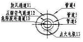
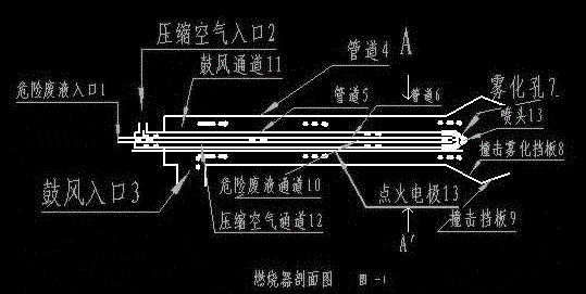
[0012] An atomizing burner for disposing of industrial hazardous waste liquid includes pipeline 4, pipeline 5, pipeline 6, hazardous waste liquid inlet 1, compressed air inlet 2, blast inlet 3, nozzle 13, impact atomization baffle 8, impact baffle Plate 9, ignition circuit 13, three pipes, with different diameters and different lengths, are concentrically nested together, shortened from the inside to the outside, forming three independent channels, hazardous waste liquid channel 10, compressed air channel 12, and blast channel 11 When igniting and burning, start the blower, blow air to the front end of the burner through the blast inlet 3, start to adjust the damper to be smaller, which is conducive to ignition, and provide waste to the burner nozzle 13 through the hazardous waste liquid inlet 1 after combustion Liquid, and then provide high-pressure air to the nozzle ...


PUM


Abstract

The invention discloses an atomizing combustor for treating industrial hazardous waste liquid. The atomizing combustor used for incineration of the industrial hazardous waste liquid with a certain heat value comprises three pipes with different diameters. The pipes sleeve one another concentrically to form three independent channels. The hazardous waste liquid enters the hazardous waste liquid channel 10 formed by the pipe 6. Compressed air enters the compressed air channel 12 formed by gaps of the pipe 5 and the pipe 6. The hazardous waste liquid and the compressed air enter a front pipe cavity to be mixed up. The mixture is discharged via an atomizing hole 7 and impacts on an impact atomizing stop plate 8 to be atomized. Air generated by an air blower is blown from the air blast channel formed by the gaps of the pipe 4 and the pipe 5, and is fully mixed with the atomized liquid sprayed from the atomizing hole 7 to combust. The atomizing combustor has the advantages that effective atomization viscosity is high, even hazardous waste liquid with some impurities can be treated, the atomizing combustor is convenient to operate, the hazardous waste liquid can combust fully, environmental pollution caused by emission of hazardous substances is reduced or avoided, and accordingly, the effect of protecting environment is achieved.

Description

technical field [0001] The invention relates to the fields of burner manufacture and industrial hazardous waste liquid incineration disposal, and more specifically relates to a liquid burner. Background technique [0002] Hazardous industrial waste has increasingly become a major factor threatening our country's environment, especially hazardous waste liquids are dumped indiscriminately, polluting air and water sources. The incineration of waste liquids is an effective way to deal with industrial hazardous waste liquids. The secondary pollution is low. The liquid burning burners on the market can only use low-viscosity, clean, and stable fuels. The structure of the atomizing nozzle is complex, and it is particularly easy to block. Disposal and incineration of industrial hazardous waste liquid with a certain calorific value. Industrial hazardous waste liquid generally has complex components and contains certain particles of impurities, and has a high viscosity. Units that dis...

Claims


Application Information

Patent Timeline
Patent Type & Authority Applications(China)
IPC IPC(8): F23G7/00F23D11/10F23D11/12F23D11/24
CPCF23G7/008F23D11/101F23D11/12F23D11/24F23G2205/20F23G2209/10F23G2900/54402
Inventor 王海升
Owner 王海升
Why Eureka
Try Eureka