Gas atomizing nozzles and atomizing devices

A gas atomization and nozzle technology, which is applied in the field of gas atomization nozzles and atomization devices, can solve the problems of poor powder sphericity and low atomization efficiency of the atomizer, so as to improve the powder yield and shape, improve the Atomization efficiency, the effect of reducing gas energy loss

Active Publication Date: 2022-07-22
中航迈特增材制造(徐州)有限公司 +1
View PDF8 Cites 0 Cited by
  • Summary
  • Abstract
  • Description
  • Claims
  • Application Information

AI Technical Summary

Problems solved by technology

[0005] The main purpose of the present invention is to provide a gas atomization nozzle and an atomization device. The atomization advantages of the slit atomizer reduce the cost of the atomizing gas, effectively improve the atomization efficiency, reduce satellite powder, hollow powder and tiny metal flakes, and significantly improve the powder yield and shape, so as to solve the problems in the existing technology. Technical problems of low atomization efficiency and poor powder sphericity of atomizer

Method used


Image

  • Gas atomizing nozzles and atomizing devices
  • Gas atomizing nozzles and atomizing devices
  • Gas atomizing nozzles and atomizing devices

Examples


Embodiment 1

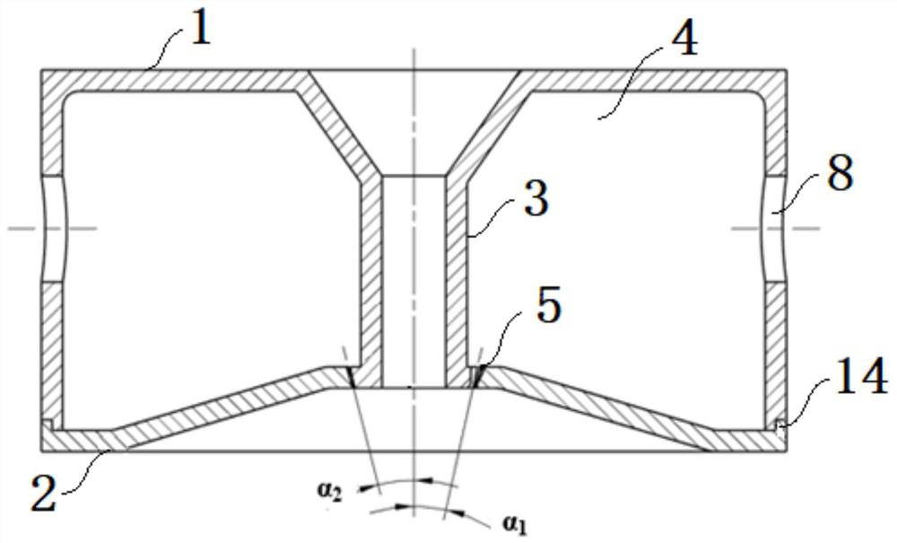
[0044] During operation, the distance between the center line of the annular hole and the center line of the annular slit between the position of the bottom end of the inner wall of the upper end cover of the atomizer cavity and the lower end cover of the cavity is 1 mm. The number of ring holes between the bottom end of the inner wall of the upper end cover of the cavity and the lower end cover of the cavity is 9, the minimum diameter of the hole is 2mm, the minimum width of the annular slit is 1.5mm, and the angle between the center line of the ring hole is α 1 =25°, the angle between the center line of the annular slit is α 2 =30°. The diversion diameter is 4mm. The metal to be atomized is 100Kg of 18Ni300 die steel. The 18Ni300 die steel material is subjected to vacuum induction melting and then atomized. During atomization, the atomizing gas is argon, and the atomizing pressure is 2.5MPa. Continuously successfully atomized 6 furnaces; -200 mesh metal powder accounts f...

Embodiment 2

[0046] During operation, the distance between the center line of the annular hole and the center line of the annular slit between the position of the bottom end of the inner wall of the upper end cover of the atomizer cavity and the lower end cover of the cavity is 0mm. The number of ring holes between the bottom end of the inner wall of the upper end cover of the cavity and the lower end cover of the cavity is 9, the minimum diameter of the hole is 2mm, the minimum width of the annular slit is 1.5mm, and the angle between the center line of the ring hole is α 1 =25°, the angle between the center line of the annular slit is α 2 = 25°. The diversion diameter is 4mm. The metal to be atomized is 100Kg of 18Ni300 die steel. The 18Ni300 die steel material is subjected to vacuum induction melting and then atomized. During atomization, the atomizing gas is argon, and the atomizing pressure is 2.5MPa. Continuously successfully atomized 6 furnaces; -200 mesh metal powder accounts f...

Embodiment 3

[0048] During operation, the distance between the center line of the annular hole and the center line of the annular slit between the position of the bottom end of the inner wall of the upper end cover of the atomizer cavity and the lower end cover of the cavity is 1 mm. The number of ring holes between the bottom end of the inner wall of the upper end cover of the cavity and the lower end cover of the cavity is 9, the minimum diameter of the hole is 2mm, the minimum width of the annular slit is 1.5mm, and the angle between the center line of the ring hole is α 1 =20°, the angle between the center line of the annular slit is α 2 = 25°. The diversion diameter is 4mm. The metal to be atomized is 100Kg of 18Ni300 die steel. The 18Ni300 die steel material is subjected to vacuum induction melting and then atomized. During atomization, the atomizing gas is argon, and the atomizing pressure is 3MPa. Continuously successfully atomized 6 furnaces; -200 mesh metal powder accounts fo...


PUM


Abstract

The invention provides a gas atomizing nozzle and an atomizing device. The gas atomizing nozzle includes an upper end cover of a cavity and a lower end cover of the cavity, one end of the upper end cover of the cavity is provided with an opening, and the upper end cover of the cavity is provided with an opening. The middle part is provided with a funnel-shaped molten metal inlet; the lower end cover of the cavity is covered at the opening of the upper end cover of the cavity, and an air cavity is formed between the upper end cover of the cavity and the lower end cover of the cavity; A Laval-type air outlet in which an annular hole and an annular slit are fitted with each other is formed between the position of the bottom end of the inner wall of the upper end cover of the cavity and the lower end cover of the cavity. The gas atomizing nozzle combines the advantages of annular hole and annular slit atomizer atomization, reduces the cost of atomization gas, effectively improves atomization efficiency, reduces satellite powder, hollow powder and tiny metal flakes, and significantly improves powder yield. It is especially suitable for metal materials with high atomization viscosity, small superheat degree and easy segregation.

Description

technical field [0001] The invention relates to the technical field of metal gas atomization, in particular to a gas atomization nozzle and an atomization device. Background technique [0002] The inert gas atomization method is a process in which the liquid metal stream is broken into small droplets and solidified into powder by high-speed air flow. Because the powder prepared by it has high purity, low oxygen content, controllable powder particle size, low production cost and high sphericity It has become the main development direction of high-performance and special alloy powder preparation technology. In the gas atomization pulverizing process, the atomizer is used as a transducer to convert the mechanical energy of the high-pressure gas and the thermal energy provided by the furnace to the surface energy of the metal. It plays an important role in stability and determines the key technical indicators such as particle size, distribution range, morphology and yield of me...

Claims


Application Information

Patent Timeline
Patent Type & Authority Patents(China)
IPC IPC(8): B22F9/08
CPCB22F9/082B22F2009/088B22F2009/0892
Inventor 杨环
Owner 中航迈特增材制造(徐州)有限公司
Why Eureka
Try Eureka