Manufacture method for composite-material cementing structural test piece with defect of air holes in glue layer

A technology of composite materials and manufacturing methods, which is applied in the direction of analyzing materials, preparing samples for testing, and using sound waves/ultrasonic waves/infrasonic waves for material analysis, etc. It can solve the problem that the size, shape and thickness of air holes in the adhesive layer cannot be quantitatively designed. problem, to achieve the effect of strengthening controllability and scalability

Active Publication Date: 2016-11-09
HUAZHONG UNIV OF SCI & TECH
View PDF8 Cites 8 Cited by
  • Summary
  • Abstract
  • Description
  • Claims
  • Application Information

AI Technical Summary

Problems solved by technology

[0005] The purpose of the present invention is to overcome the above-mentioned shortcomings of the prior art, and provide a method for making a composite material bonded structure defect test block containing air holes in the glue layer, which is used to realize the simulation of the glue layer in the composite material multilayer bonded structure. air hole defects in the adhesive layer, solving technical problems such as the size, shape and thickness of the air hole defects in the adhesive layer that cannot be quantitatively designed in the existing technology

Method used


Image

  • Manufacture method for composite-material cementing structural test piece with defect of air holes in glue layer
  • Manufacture method for composite-material cementing structural test piece with defect of air holes in glue layer
  • Manufacture method for composite-material cementing structural test piece with defect of air holes in glue layer

Examples


Embodiment Construction

[0024] In order to make the object, technical solution and advantages of the present invention clearer, the present invention will be further described in detail below in conjunction with the accompanying drawings and embodiments. It should be understood that the specific embodiments described here are only used to explain the present invention, not to limit the present invention. In addition, the technical features involved in the various embodiments of the present invention described below can be combined with each other as long as they do not constitute a conflict with each other.

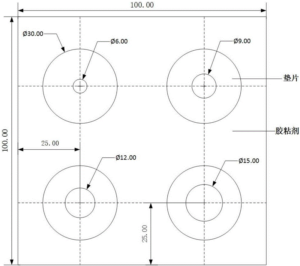
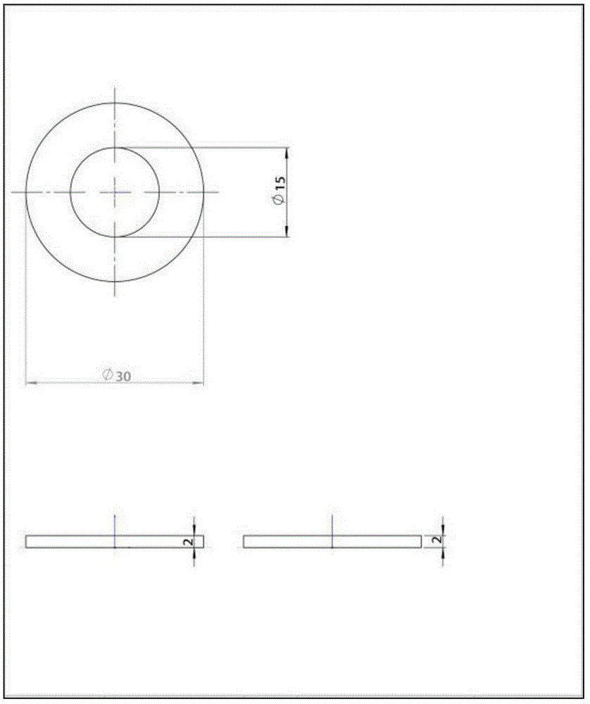
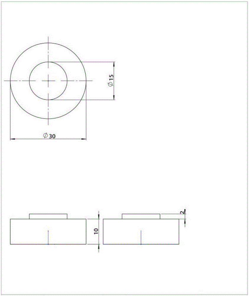
[0025] In this embodiment, a cylindrical hole defect is taken as an example. According to the detection requirements, after designing the structure of the composite bonded structure test block (including the number of layers of the test block and the shape of the test block), proceed as follows:

[0026] 1. Design of air hole defects

[0027] According to the nature and size of the composite m...


PUM


Abstract

The invention provides a manufacture method for a composite-material cementing structural test piece with a defect of air holes in a glue layer, and belongs to non-destructive detection field. The method realizes simulation of the air hole defect in the glue layer of the composite-material multi-layer cementing structure by employing 3D printing technology for preparing a glue-layer pad, and solves the technical problems that the size, shape, thickness and the like of an air hole defect in the glue layer cannot be quantitatively designed by employing the prior art. The method possesses the advantages of real and reliable simulation, high quantization precision, good expandability and the like.

Description

technical field [0001] The invention belongs to the field of non-destructive testing, and relates to a method for manufacturing a defect test block, in particular to a method for manufacturing a defect test block of a composite material bonding structure with air holes in the glue layer. Background technique [0002] Non-destructive testing technology uses the phenomenon that some physical properties of substances change due to defects or differences in organizational structure, and uses physical methods to measure these changes without destroying the performance, external shape and internal structure of the test object. It is a special detection technology to achieve the purpose of understanding and evaluating the nature, state, quality or internal structure of the detection object. At present, non-destructive testing technology has been widely used in machinery and equipment manufacturing, metallurgy, petrochemical industry, weapons, ships, aviation and aerospace, nuclear ...

Claims


Application Information

Patent Timeline
Patent Type & Authority Applications(China)
IPC IPC(8): G01N29/30G01N1/28
CPCG01N1/28G01N29/30G01N2001/2893
Inventor 杨振刚王可嘉刘劲松王天一周宇李文军游承武
Owner HUAZHONG UNIV OF SCI & TECH
Why Eureka
Try Eureka