A Method for Locating and Identifying Cable Partial Discharge

A partial discharge and identification method technology, applied in the direction of measuring electricity, measuring electrical variables, testing dielectric strength, etc., can solve the problems of increasing waveform rising edge time, decreasing fault traveling wave amplitude, and high possibility of partial discharge, etc. , to achieve the effect of reliable principle, low misjudgment rate and high reliability

Active Publication Date: 2019-03-12
SHANGHAI MUNICIPAL ELECTRIC POWER CO +1
View PDF4 Cites 0 Cited by
  • Summary
  • Abstract
  • Description
  • Claims
  • Application Information

AI Technical Summary

Problems solved by technology

[0007] ①f: The same signal appears at multiple frequencies at the same time → the possibility of partial discharge is high
[0009] ③n: The signal pulse repetition rate is higher than 30 times per second (pps) → the possibility of partial discharge is high
[0010] ④q: The signal is under the same voltage, and the level is roughly the same → there may be partial discharge
[0011] ⑤t: The signal continues to appear for a long time → there may be partial discharge
[0026] like image 3 As shown, in practice, the fault traveling wave waveform is attenuated by the cable during the transmission process, causing the fault traveling wave amplitude to gradually decrease, and the rising edge time of the waveform to increase

Method used


Image

  • A Method for Locating and Identifying Cable Partial Discharge
  • A Method for Locating and Identifying Cable Partial Discharge
  • A Method for Locating and Identifying Cable Partial Discharge

Examples


Embodiment 1

[0071] Such as Figure 6 As shown, in the cable line, the partial discharge sensor 1 is only installed on one of the insulating joints, and the signal collected by the sensor is converted by the electro-optic signal sending device (E / O) and then transmitted to the positioning device placed in the background through optical fiber. , the positioning device performs unified processing on the waveform signals detected at different times, based on the echo positioning principle of traveling waves, this principle is to calibrate the position of the discharge point or noise by calculating the time difference between the first wave and the echo of the signal, In combination with the partial discharge discrimination method mentioned in the present invention, the position of the partial discharge point is displayed and output.

Embodiment 2

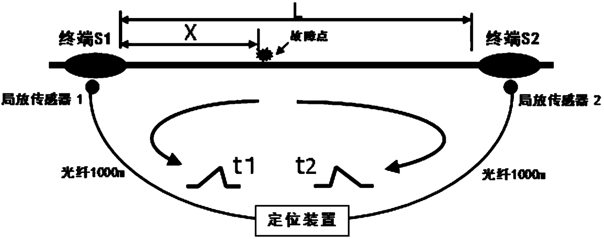
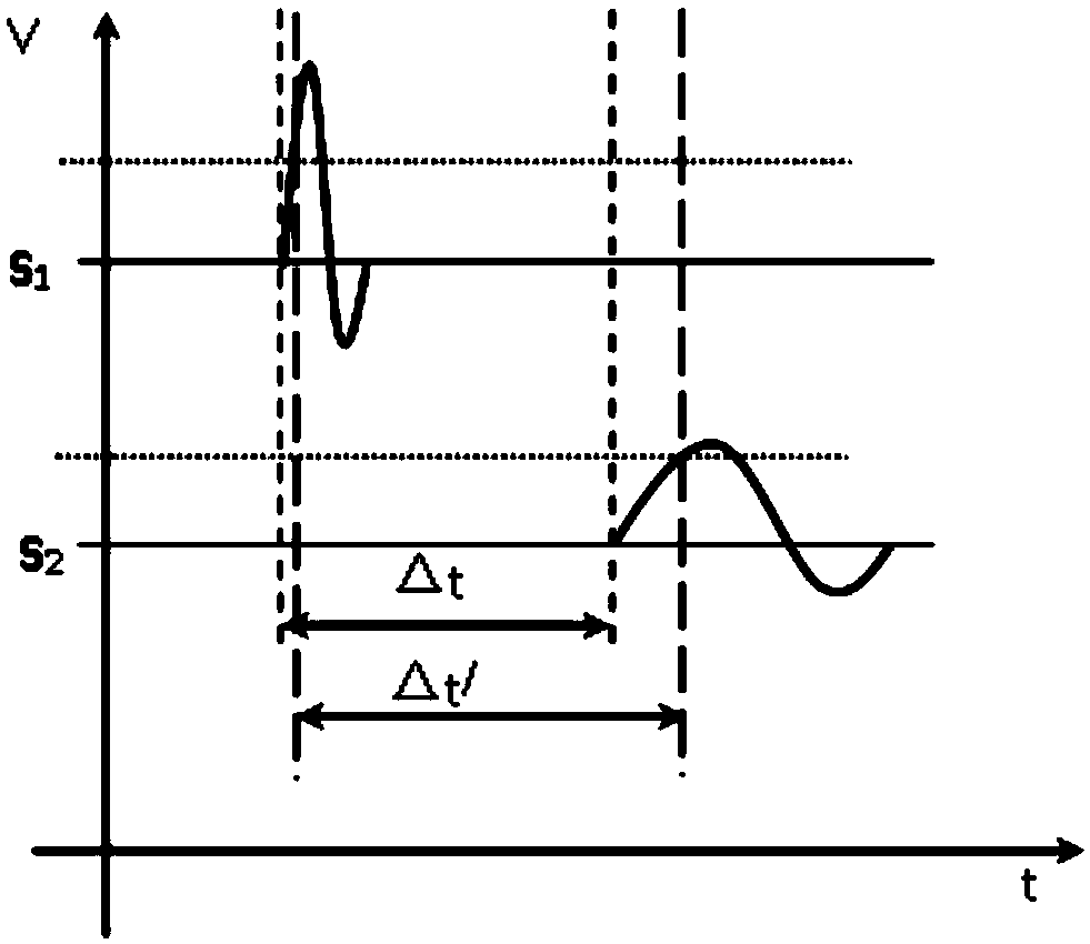
[0073] When the line is long, the echo of the traveling wave may be attenuated and deformed due to long-distance propagation, and eventually cannot be used for positioning. A partial discharge discrimination method based on the double-terminal time difference method can be used. Such as Figure 7 As shown, in the cable line, PD sensors are respectively installed on the two insulating joints, which are respectively PD sensors 1 and 2. The signals collected by the sensors are converted by the electro-optic signal sending device (E / O) It is transmitted to the positioning device installed in the background. The positioning device performs unified processing on the two sets of detection waveform signals collected at the same time. The partial discharge positioning program performs positioning calculation on this group of detection waveforms. The position of the point is matched with the partial discharge discrimination method mentioned in the present invention to display and output...

Embodiment 3

[0075] When there are enough points available for monitoring in the line, the multiple time difference positioning method composed of multiple sets of detection waveforms can be used to perform multiple calibrations on partial discharge points to improve positioning accuracy. Such as Figure 8 As shown, in the cable line, PD sensors are installed on the three insulated joints, which are respectively PD sensors 1, 2, and 3. The signals collected by the sensors are converted by the electro-optic signal sending device (E / O) Afterwards, it is transmitted to the positioning device placed in the background through optical fiber. The positioning device performs unified processing on the three sets of detection waveform signals collected at the same time and then measures multiple sets of time differences. The partial release positioning program performs multiple positioning calculations on this group of detection waveforms , based on the principle of multiple positioning, the locatio...


PUM


Abstract

The invention relates to a cable partial discharge positioning and identification method, comprising the steps of: 1) a positioning device detecting current traveling-wave signals in real time through a partial discharge detector installed on a cable line to be detected; 2) according to abnormal traveling-wave signals in the current traveling-wave signals, obtaining positions which may generate partial discharge on the cable line, and constructing an X-q-t three-dimensional distribution map according to the positions which may generate partial discharge in the abnormal traveling-wave signals, signal size and time; and 3) according to the X-q-t three-dimensional distribution map, screening accurate positions generating partial discharge from the positions which may generate partial discharge through a partial discharge signal determination method. Compared with the prior art, the cable partial discharge positioning and identification method can position before determination, and has the advantages of reliable principle, sound distinguishing effect, and high precision.

Description

technical field [0001] The invention relates to the technical field of partial discharge detection of power cable lines, in particular to a method for locating and identifying cable partial discharge. Background technique [0002] Existing technical solutions: [0003] Discrimination Method of Partial Discharge State Based on Pulse Current Method [0004] In addition to the transfer of charges and the loss of electrical energy, the generation of partial discharge also produces electromagnetic radiation, ultrasonic waves, light emission, heat generation, and new products. Therefore, for these phenomena, the basic methods of partial discharge detection include pulse current method, ultra-high frequency method, ultrasonic method, spectroscopic method and chemical detection method. Among them, the pulse current method is widely used because of its following advantages: ① The discharge current pulse information is rich, and the severity of the discharge can be judged by the sta...

Claims


Application Information

Patent Timeline
Patent Type & Authority Patents(China)
IPC IPC(8): G01R31/12
CPCG01R31/1272
Inventor 钱天宇林波史晓俊沈寅喆王骁迪崔亮吕渊陈佳金毅严其强张屹陈立荣东盛刚周智鹏唐敏玲何明勇
Owner SHANGHAI MUNICIPAL ELECTRIC POWER CO
Why Eureka
Try Eureka