Pseudo range phase integrated ionosphere delay solving method

A technology of ionospheric delay and pseudorange phase, applied in radio wave measurement system, satellite radio beacon positioning system, measurement device, etc., can solve problems based only on pseudorange observation value, achieve simple algorithm, improve accuracy and reliability sexual effect

Inactive Publication Date: 2016-11-09
SHANGHAI ASTRONOMICAL OBSERVATORY CHINESE ACAD OF SCI
View PDF4 Cites 7 Cited by
  • Summary
  • Abstract
  • Description
  • Claims
  • Application Information

AI Technical Summary

Problems solved by technology

Considering the complexity of the above phase data processing, the existing satellite naviga

Method used


Image

  • Pseudo range phase integrated ionosphere delay solving method
  • Pseudo range phase integrated ionosphere delay solving method
  • Pseudo range phase integrated ionosphere delay solving method

Examples


Embodiment Construction

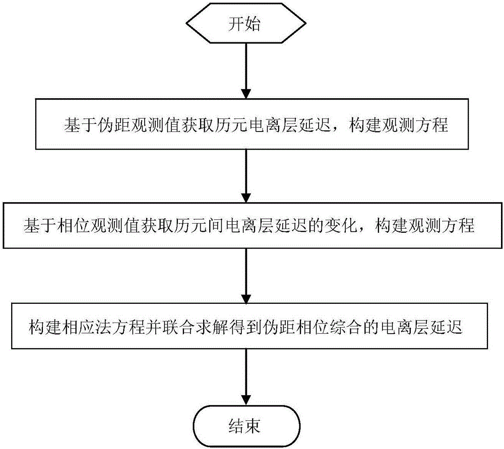
[0060] The method for solving the ionospheric delay of pseudorange phase integration according to the present invention will be further described in detail below in conjunction with the accompanying drawings and specific embodiments.

[0061] figure 1 The flow chart of the ionospheric delay solution method for pseudorange phase synthesis described in the present invention in an implementation manner is illustrated.

[0062] Such as figure 1 As shown, the ionospheric delay solution method of the pseudorange phase synthesis described in the present invention includes steps in an implementation mode:

[0063] Divide the processing arc into n epochs t i , where i=1,2...n;

[0064] Obtain epoch t based on pseudorange observations i ionospheric delay and delay the ionosphere Construct the observation equation as observations:

[0065] I ^ t i - I ...


PUM


Abstract

The invention discloses a pseudo range phase integrated ionosphere delay solving method which includes the steps of obtaining epoch ionosphere delay based on pseudo range observed value and constructing an observation equation, obtaining the change of ionosphere delay between epochs based on phase observed value and constructing an observation equation, constructing a corresponding method equation and jointly solving the pseudo range phase integrated ionosphere delay. The absolute ionosphere delay amount is solved by using the pseudo range observed value, and the ionosphere delay changing amount is solved by using the differential phase observed value between epochs. The integration is conducted based on the basis to solve convergence problem in a phase smooth pseudo range observed value method. The method does not rely on long-term continuity of phase data, prevents fuzziness resolving by using phase observed value, and improve the solving precision and reliability of the ionosphere delay. The method is applicable to satellite basic navigation and ionosphere delay calculation in satellite-based enhanced system, and calculation of ionosphere delay correction number for user positioning and service system.

Description

technical field [0001] The invention relates to an ionospheric delay solution method in the field of satellite navigation, in particular to a pseudorange phase synthesis ionospheric delay solution method. Background technique [0002] Global Navigation Satellite System (GNSS) refers to a system that uses electromagnetic waves emitted by navigation satellites to locate, navigate and time objects on the earth. Currently, it includes GPS in the United States, GLONASS in Russia, and GALILEO in Europe. And our country's BDS system. The user can obtain the position of the receiver at that instant by obtaining the distance from the satellite and the phase observation value through the receiver observation. [0003] The error sources that affect the service performance of satellite navigation systems mainly include: satellite orbit error, satellite clock error, tropospheric error, ionospheric error, and observation multipath error. The ionosphere is an ionized atmosphere with a he...

Claims


Application Information

Patent Timeline
IPC IPC(8): G01S19/07
CPCG01S19/07
Inventor 陈俊平房成贺杨赛男巩秀强陈倩
Owner SHANGHAI ASTRONOMICAL OBSERVATORY CHINESE ACAD OF SCI
Why Eureka
Try Eureka