Method and device for separating roll core and shell of waste lithium ion battery

A lithium-ion battery and separation method technology, which is applied in the field of separation method and equipment for waste lithium-ion battery cores and shells, can solve the problem of bulging battery shape, high requirements for cutting knife material and hardness, and short-circuiting of batteries. Fire and other problems to achieve the effect of reducing adhesion

Active Publication Date: 2016-11-09
HEFEI GUOXUAN HIGH TECH POWER ENERGY
View PDF5 Cites 13 Cited by
  • Summary
  • Abstract
  • Description
  • Claims
  • Application Information

AI Technical Summary

Problems solved by technology

At present, the materials of lithium-ion battery casings are generally steel, aluminum, etc., and mechanical cutting or physical crushing are generally used to separate them. However, this traditional method will introduce metal chips into the battery cell during the implementation process and cause a short circuit. Or misplaced and cut to the positive and negative poles, resulting in the phenomenon of battery short circuit and ignition
Moreover, the continuous cutting operation using this method will cause greater wear and tear on the cutting knife or abrasive tool. In addition, the requirements for the material and hardness of the cutting knife are also relatively high.
[0004] When dealing with scrap lithium-ion batteries, most of the battery shapes will bulge to varying degrees. The traditional cutting method is simply to cut the shell, and because the winding core and the shell are often bonded tightly, the winding core and the shell are often bonded tightly. The separation of the shell may still require other external forces

Method used


Image

  • Method and device for separating roll core and shell of waste lithium ion battery
  • Method and device for separating roll core and shell of waste lithium ion battery
  • Method and device for separating roll core and shell of waste lithium ion battery

Examples


Embodiment 1

[0044] A method for separating waste lithium-ion battery winding cores and casings, comprising the following steps:

[0045] (1) Fix the square lithium battery horizontally, and make its cover 2mm outside the fixing table;

[0046] (2) Use a cutter to cut the upper and lower end faces of the square lithium battery case below the cover at the same time. The depth of the cut is 40% of the wall thickness of the case, resulting in incomplete cut marks;

[0047] (3) Fix the cover plate of the square lithium battery, and use a thimble to insert the explosion-proof hole on the cover plate of the square lithium battery, and pass high-pressure inert helium gas with a pressure of 6Kg into it to break the cut mark, and The casing of the prismatic lithium battery is washed off by high-pressure gas and separated;

[0048] (4) Cut off the tab between the cover plate and the core to separate the cover plate from the core.

Embodiment 2

[0050] A method for separating waste lithium-ion battery winding cores and casings, comprising the following steps:

[0051] (1) Fix the square lithium battery horizontally, and make its cover 3mm outside the fixing table;

[0052] (2) Use a cutter to cut the upper and lower end faces of the square lithium battery case below the cover at the same time. The depth of the cut is 60% of the wall thickness of the case, resulting in incomplete cut marks;

[0053] (3) Fix the cover plate of the square lithium battery, and use a thimble to insert into the explosion-proof hole on the cover plate of the square lithium battery, and pass high-pressure inert nitrogen gas with a pressure of 10Kg into it to break the cut mark and make it The casing of the prismatic lithium battery is washed down by high-pressure gas and separated;

[0054] (4) Cut off the tab between the cover plate and the core to separate the cover plate from the core.

Embodiment 3

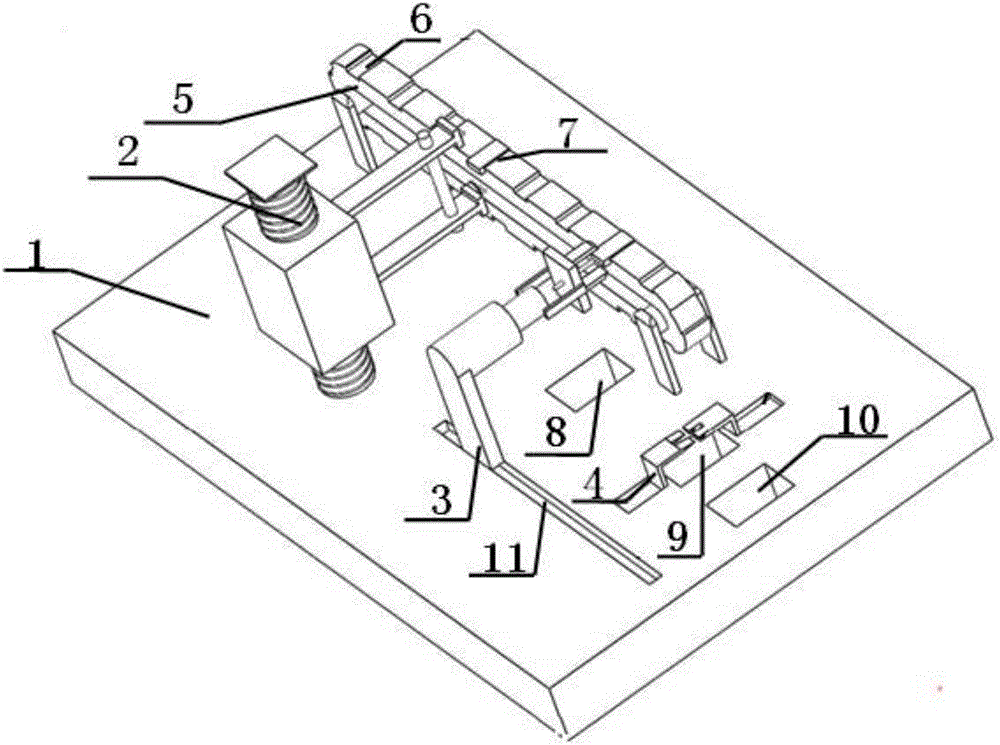
[0056] like figure 1 As shown, a separation device for waste lithium-ion battery winding cores and shells includes a working platform 1, a conveyor belt 5 is fixed on one side of the working platform 1, and a square conveyor belt 5 is fixed on the other side of the working platform 1. The shell of the lithium battery 7 is cut and blasted by a pre-cutting mechanism 2 and a high-pressure blasting mechanism 3. The working platform 1 located directly below the high-voltage blasting mechanism 3 is provided with a shell discharge port 8, which is far away from the work at the end of the pre-cutting mechanism 2. The platform 1 is provided with a winding core discharge port 9 and a cover plate discharge port 10 in sequence; a tab cutting mechanism 4 for cutting the tabs of the square lithium battery 7 is fixed above the core discharge port 9 .

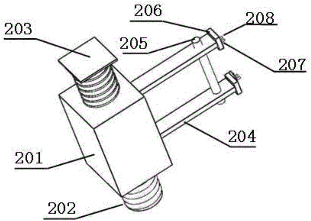
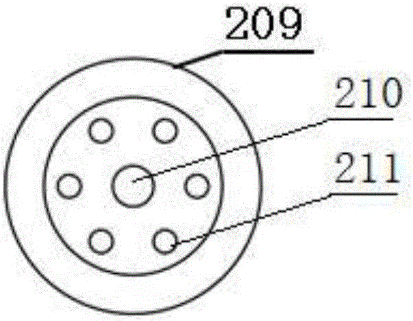
[0057] like figure 2 As shown, the pre-cutting mechanism 2 includes a pillar 203 and a circular cutter 209 fixed on the working platform 1,...


PUM


Abstract

The invention discloses a method and device for separating a roll core and a shell of a waste lithium ion battery. The method comprises the steps that the square lithium ion battery is flatly fixed, and a cover plate of the lithium ion battery is made to be located on the outer portion of a fixing table; cutters are used for cutting the upper end face and the lower end face of the part, below the cover plate, of the shell of the square lithium ion battery, and an incomplete cut mark is formed; the cover plate of the square lithium ion battery is fixed, an ejector pin is used for being inserted into an anti-explosion hole in the cover plate of the square lithium ion battery, high-pressure inert gas is introduced into the anti-explosion hole, breakage occurs at the part of the cut mark, and the shell of the square lithium ion battery is rushed by the high-pressure gas and falls to be separated; a pole lug between the cover plate and the roll core is cut off, and the cover plate and the roll core are separated. By means of the pre-cutting and high-pressure gas pressurization, the shell and the cover plate are broken along the cut mark defect position, and the shell is rushed by the high-pressure gas and falls to be separated, so that the risk of short circuiting caused when metal enters in the cutting process is avoided, the cover plate and the roll core of the battery in deformation expansion are easily separated, and the method is safe, stable and efficient.

Description

technical field [0001] The invention belongs to the technical field of lithium ion batteries, and in particular relates to a separation method and equipment for a waste lithium ion battery winding core and casing. Background technique [0002] Lithium-ion batteries are widely used because of their excellent electrochemical performance, especially in recent years with the development of new energy vehicle industry, more and more lithium-ion batteries are widely used in electric vehicles. However, the lifespan of general lithium-ion batteries is generally 5 to 8 years. With the end of the service life of lithium-ion batteries, the issue of recycling them is particularly important. [0003] At present, the lithium-ion battery recycling method is generally to carry out mechanical separation first and then carry out wet treatment to recycle valuable materials. In the recycling step, the shell and the winding core must first be separated before subsequent processing can begin. ...

Claims


Application Information

Patent Timeline
Patent Type & Authority Applications(China)
IPC IPC(8): H01M10/54H01M10/0525
CPCH01M10/0525H01M10/54Y02E60/10Y02W30/84
Inventor 臧强王双双姜雨恒曹利娜
Owner HEFEI GUOXUAN HIGH TECH POWER ENERGY
Why Eureka
Try Eureka