
Miniature high-isolation microwave double-frequency power divider

A technology of high isolation and power divider, which is applied in the direction of waveguide devices, electrical components, connecting devices, etc., can solve the problems of mutual influence of output signals, unfavorable miniaturization design, and short distance between two output ports.

Active Publication Date: 2016-11-09
GUANGDONG UNIV OF TECH
View PDF11 Cites 2 Cited by
  • Summary
  • Abstract
  • Description
  • Claims
  • Application Information

AI Technical Summary

Problems solved by technology

[0004] 1. Use the structure of ordinary microstrip line to design the power divider. This design scheme will cause the distributed capacitance and inductance that is easy to form after welding the isolation components to affect the performance of the circuit, and it occupies a large size.
[0005] 2. Use the structure of coupled lines to design the power divider. In this design scheme, the distance between the two output ports will be too short, causing the output signals to affect each other.
[0006] 3. The coupling line is added to extend the microstrip line structure of the output port. This design effectively overcomes the parasitic effect formed by welding isolation components and the problem of too short output port distance, but the additional access to extend the output port The design size is too large due to the microstrip line, which is not conducive to the miniaturization design
[0007] The power dividers in the prior art all connect the isolation element in parallel at the end of the output port, and the power divider with this structure causes a large coupling effect between the output ports

Method used


Image

  • Miniature high-isolation microwave double-frequency power divider
  • Miniature high-isolation microwave double-frequency power divider
  • Miniature high-isolation microwave double-frequency power divider

Examples


Embodiment 1

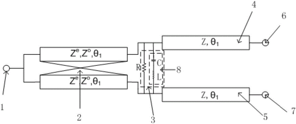
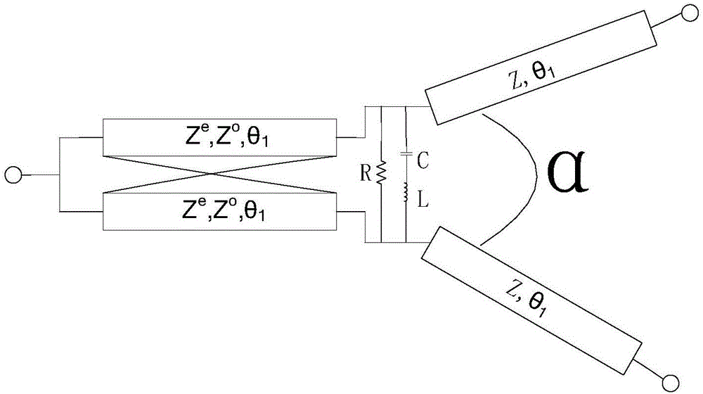
[0045] This embodiment discloses a miniaturized high-isolation microwave dual-frequency power divider, such as Figure 1a and 1b As shown, it includes an input port 1, a coupled line 2, an isolation network 3, a first transmission line 4, a second transmission line 5, a first output port 6 and a second output port 7, and the coupled line 2 includes a first port and the second port, and the third port and the fourth port at the other end of the coupled line 2.

[0046] The input port 1 is connected to the first port and the second port of the coupled line 2, the third port of the coupled line 2 is connected to the first output port 6 through the first transmission line 5, and the fourth port of the coupled line 2 is connected to the second port through the second transmission line 5. Output port 7; the connection between the third port of the coupling line 2 and the first transmission line 4 is connected to one end of the isolation network 3, and the connection between the four...


PUM


Abstract

The invention discloses a miniature high-isolation microwave double-frequency power divider. The miniature high-isolation microwave double-frequency power divider comprises an input port, a coupling wire, an isolation network, a first transmission wire, a second transmission wire, a first output port and a second output port. The input port is connected with the first transmission wire and the second transmission wire through the coupling wire. The first transmission wire and the second transmission wire are respectively connected with the first output port and the second output port in correspondence. The isolation network is arranged between the coupling wire and the first transmission wire, the second transmission wire. By adopting the tail non-isolation network of the microwave double-frequency power divider, the size of the power divider and the coupling effect among output ends are effectively reduced, the isolation degree is improved, the circuit structure is compact, the design method is flexible and various, and the practical application range of the conventional microwave double-frequency power divider is greatly expanded.

Description

technical field [0001] The invention relates to a power splitter, in particular to a miniaturized high-isolation microwave dual-frequency power splitter. Background technique [0002] With the rapid development of mobile communications, the use of microwave frequency bands is becoming more and more crowded. At the same time, the integration of radio frequency circuits is becoming more and more demanding. In addition to requiring excellent performance, low cost, low loss, small size and light weight are also proposed Therefore, radio frequency components that can transmit signals in two frequency bands or even multiple frequency bands at the same time are the development trend of today's mobile communication systems. The microwave dual-frequency power amplifier is one of the key components of the radio frequency system and the communication system. With the rapid development of communication technology and the intensification of competition in the communication industry, in t...

Claims


Application Information

Patent Timeline
IPC IPC(8): H01P5/16
CPCH01P5/16
Inventor 林福民张逸松
Owner GUANGDONG UNIV OF TECH
Learn More