

Liquid spray device and surgical device
A technology of jetting device and liquid, which is applied in the direction of fluid jet scalpel, liquid variable volume machine, surgery, etc., which can solve the problems of dirtying the operating area and scattering.
- Summary
- Abstract
- Description
- Claims
- Application Information
AI Technical Summary
Problems solved by technology
Method used
Image

Examples
no. 1 approach
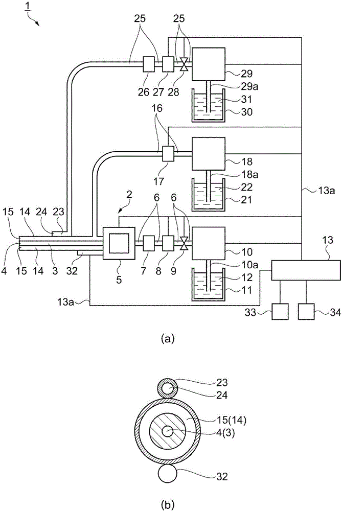
[0073] In this embodiment, according to Figure 1 to Figure 6 A liquid ejecting device as a surgical instrument will be described. figure 1 (a) is a block diagram showing the configuration of the liquid ejecting device. figure 1 (b) is a partially schematic side view showing the configuration of the nozzle of the liquid ejecting device. The liquid ejecting device 1 of the present embodiment is a medical device used in medical institutions, and has a function as a scalpel for incising or excision of an affected area by ejecting a fluid to the affected area.
[0074] like figure 1 As shown in (a), the liquid ejecting device 1 includes a handle 2 . The handle 2 is an instrument that the operator holds and operates when performing an operation. A fluid flow path, that is, an injection pipe 3 is provided on the handle 2 . One end of the spray pipe 3 is provided with a nozzle 4 serving as a liquid spray opening for spraying a fluid. The other end of the injection pipe 3 is pro...
no. 2 approach
[0164] Next, use Figure 7 as well as Figure 8 One embodiment of the liquid ejecting device will be described. Figure 7 (a) is a block diagram showing the configuration of the liquid ejecting device. Figure 7 (b) is a partially schematic side view showing the configuration of the nozzle of the liquid ejecting device. Figure 8 is a schematic diagram illustrating the behavior of a liquid in a nozzle. This embodiment differs from the first embodiment in that figure 1 The arrangement of the suction pipe 14 and the supply pipe 23 shown in FIG. In addition, descriptions of the same points as in the first embodiment are omitted.
[0165] That is, in this embodiment, if Figure 7 As shown in (a), the liquid ejecting device 80 includes a handle 81 . A suction pipe 14 is provided to surround the injection pipe 3 , and a supply pipe 82 is provided to surround the suction pipe 14 . A supply port 83 is provided at the tip of the supply pipe 82 . The nozzle 4, the suction port ...
no. 3 approach
[0170] Next, use Figure 9 as well as Figure 10 One embodiment of the liquid ejecting device will be described. Figure 9 (a) is a block diagram showing the configuration of the liquid ejecting device. Figure 9 (b) is a partially schematic side view showing the configuration of the nozzle of the liquid ejecting device. Figure 10 is a schematic diagram illustrating the behavior of a liquid in a nozzle. This embodiment differs from the first embodiment in that figure 1 The arrangement of the suction pipe 14 and the supply pipe 23 shown in FIG. In addition, descriptions of the same points as in the first embodiment are omitted.
[0171] That is, in this embodiment, if Figure 9 As shown in (a), the liquid ejecting device 86 includes a handle 87 . A supply pipe 88 is provided to surround the injection pipe 3 , and a supply port 89 is provided at the tip of the supply pipe 88 . A suction pipe 90 is provided to surround the supply pipe 88 , and a suction port 91 is provid...
PUM
 Abstract
Description
Claims
Application Information