

Wheel rim manufacturing method and automobile wheel rim manufacturing method
A manufacturing method and rim technology, applied in the direction of wheel manufacturing, wheels, rims, etc., can solve problems such as easy thinning of walls, and achieve the effect of good dimensional accuracy
- Summary
- Abstract
- Description
- Claims
- Application Information
AI Technical Summary
Problems solved by technology
Method used
Image

Examples
no. 1 Embodiment approach
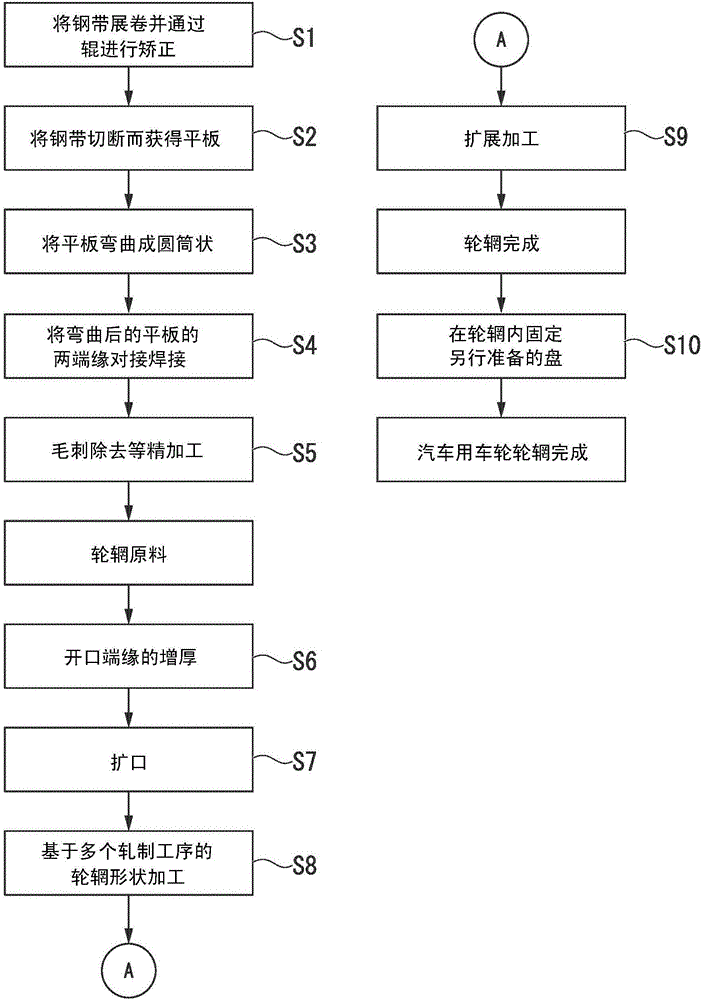
[0052] In the method for manufacturing a wheel rim for an automobile according to the first embodiment of the present invention, a pair of opening edges (hereinafter, sometimes referred to as "peripheral edge portions". figure 2 In the pair of ring-shaped parts represented by symbol 21), at least one of the thickening step S6 is thickened, the two opening edges of the rim raw material are enlarged in diameter S7, and the rim raw material is formed into a rim shape. A plurality of rolling steps S8 and an expanding step S9 for adjusting the diameter of the rim result in the completion of the rim.
[0053] As an example of the above-mentioned rim shape, the Figure 12 The same as the above-mentioned rim 1a described in , the shape including the groove 2, the wheel wells 3a, 3b, the boss 4, the bezel seating surfaces 5a, 5b, and the flanges 6a, 6b can be adopted.
[0054] The specific contents of the above-mentioned expanding step S7 and the above-mentioned rolling step S8 are no...
no. 2 Embodiment approach
[0096] Next, a method for manufacturing an automobile wheel rim according to a second embodiment of the present invention will be described. This embodiment corresponds to a modified example of the above-mentioned first embodiment, and the differences from the above-mentioned first embodiment will be mainly described, and the rest are the same as the above-mentioned first embodiment, and redundant description will be omitted.
[0097] In the present embodiment, for the heating temperature in the above-mentioned heating region 22, at Figure 5 A temperature gradient is added in the up-and-down direction (the axis direction of the rim material 20) of the paper.
[0098] That is, heating is performed by adding a temperature gradient as follows: in the heating region 22, the temperature at the front end edge of the opening that is in contact with the annular groove 11 and receives a compressive load first is the highest, and the temperature increases as the distance from the front...
Embodiment
[0111] In order to confirm the effect of the manufacturing method of the automobile wheel rim according to the first embodiment, the following confirmation based on the examples was performed.
[0112] That is, first, prepare a plurality of flat plates of high-strength steel (thickness is 2.36mm and 2.00mm, yield stress is 800N / mm 2 ), these flat plates are respectively bent into cylindrical shapes and the two ends are butt-welded to obtain two kinds of cylindrical rim raw materials (the radius of the respective outer peripheral surfaces is 170mm, and the width dimension parallel to the axial direction of the cylinder is 202mm ).
[0113] Next, the peripheral portion of each cylindrical rim raw material is thickened and expanded, and then formed into a rim shape by a rolling process.
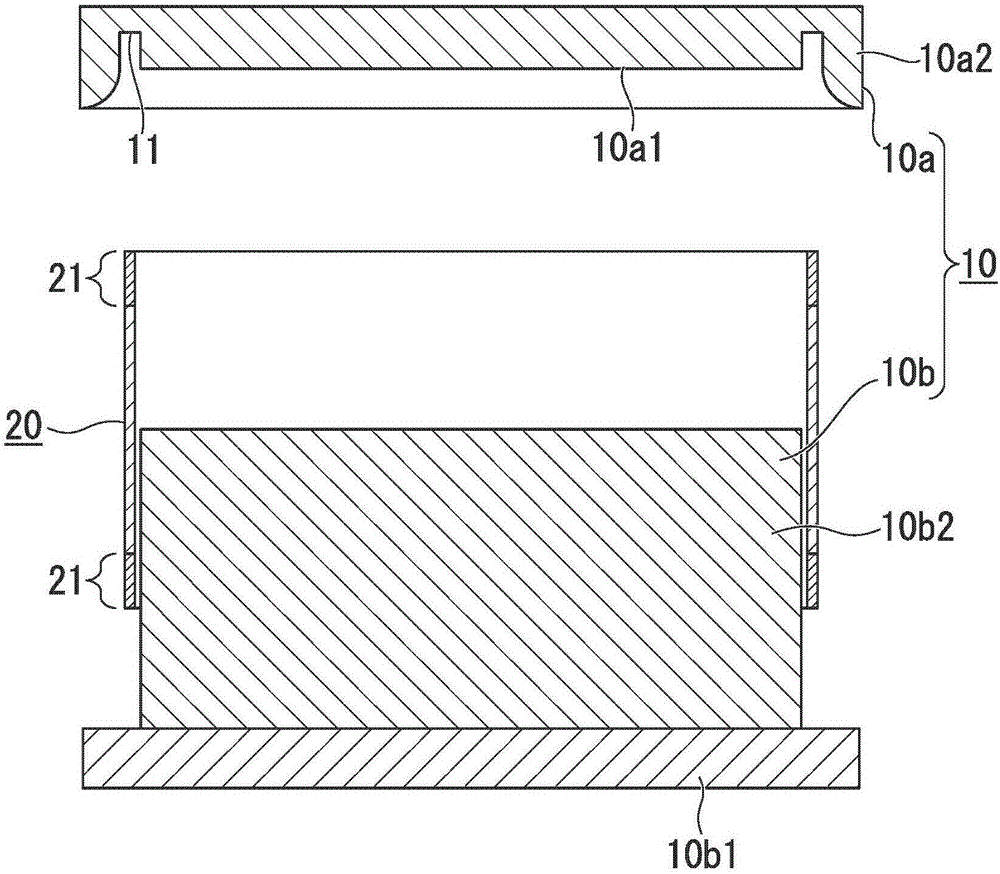
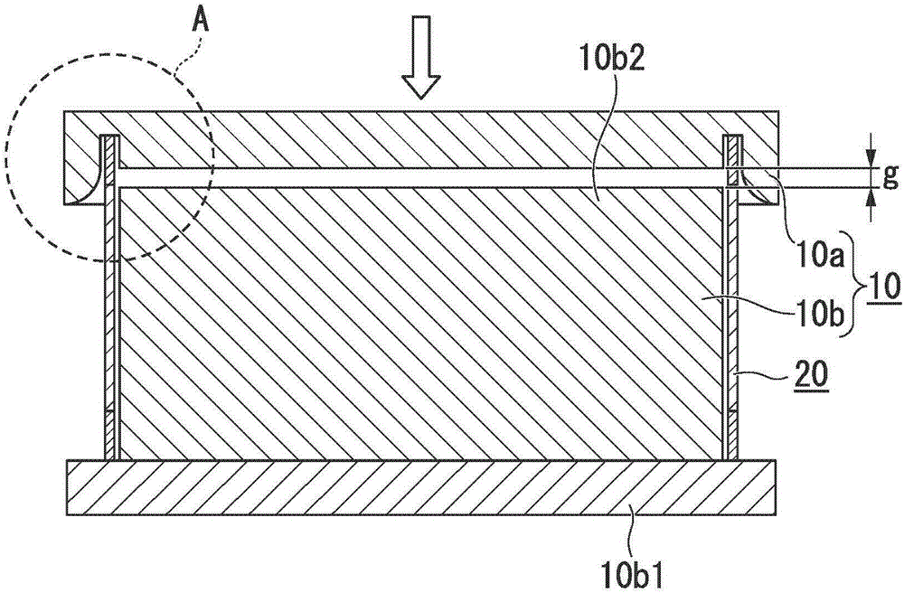
[0114] In the thickening step S6 of thickening the peripheral part, after preheating the peripheral part to 700°C, use Figure 4A ~ Figure 4D The illustrated punching die 10a and support die 1...
PUM
| Property | Measurement | Unit |
|---|---|---|
| Thickness | aaaaa | aaaaa |
| Yield stress | aaaaa | aaaaa |
| Thickness | aaaaa | aaaaa |
Abstract
Description
Claims
Application Information