Solid waste size reduction treatment device

A processing device and technology for solid waste, applied in the direction of grain processing, etc., can solve the problems of high cost of solid waste treatment, impact on the marine ecological environment, and high labor intensity of workers, and achieve long-term overseas navigation convenience, widening the size range, and compact structure. Effect

Inactive Publication Date: 2016-11-16
GUANGDONG IND TECHN COLLEGE
View PDF6 Cites 2 Cited by
  • Summary
  • Abstract
  • Description
  • Claims
  • Application Information

AI Technical Summary

Problems solved by technology

[0002] At present, in the occasions where it is inconvenient to dispose of solid domestic waste on site, such as ocean-going ships, the treatment methods for solid domestic waste other than kitchen waste mainly include the following: (1) directly throwing solid waste into the sea for natural degradation, This method has a long degradation cycle and has a serious impact on the marine ecological environment. At present, some countries have legislated to prohibit this treatment; (2) Centralized stacking and handing over to the municipal government after landing. This method requires a large space for other For ships with limited space, this treatment method is not ideal; (3) first use solid waste treatment equipment for volume reduction treatment, and then collect them collectively. This treatment method requires less space, but currently there are Most solid waste treatment devices generally adopt a single-axis or double-axis hob structure, which is cumbersome to operate and requires a large number of manual auxiliary operations. The labor intensity of workers is high, and the cost of solid waste treatment is too high, which is not conducive to popularization and application.

Method used


Image

  • Solid waste size reduction treatment device
  • Solid waste size reduction treatment device
  • Solid waste size reduction treatment device

Examples


Embodiment 1

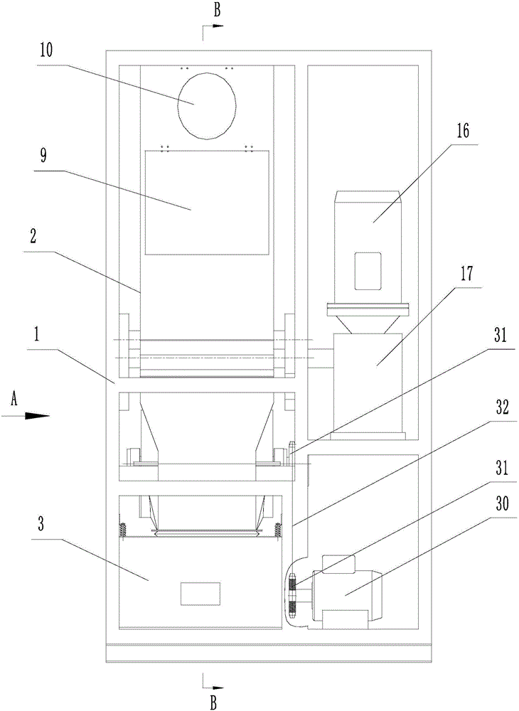
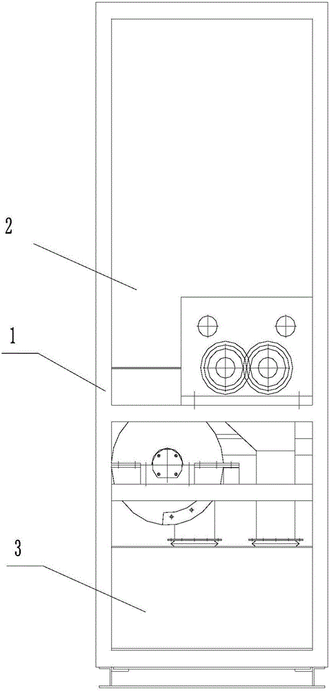
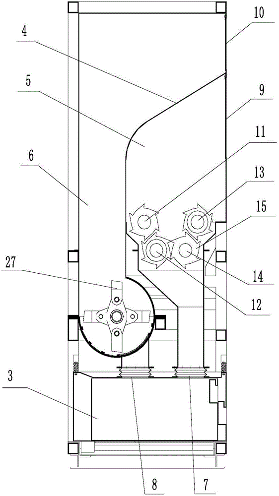
[0036] In this embodiment, a solid waste volume reduction treatment device, such as Figure 1 to Figure 3As shown, it includes frame 1, hopper 2, slag receiving box 3, hob crushing mechanism, hob driving mechanism, hammer breaking mechanism and hammer driving mechanism. The hopper is installed on the upper part of the frame, and the slag receiving box is installed on the frame. In the lower part, there is a partition 4 inside the hopper, and the partition divides the inner cavity of the hopper into a hob crushing chamber 5 and a hammer crushing chamber 6. The hob crushing mechanism is installed in the hob crushing chamber, and the hammer crushing chamber is installed Mechanism, the hob crushing mechanism is connected with the hob driving mechanism, the hammer breaking mechanism is connected with the hammer driving mechanism, and both the hob driving mechanism and the hammer driving mechanism are installed on the frame. The hopper is divided into two independent processing cham...

Embodiment 2

[0050] This embodiment is a solid waste volume reduction treatment device. Compared with Embodiment 1, the difference lies in that: in the hammer crushing cavity, a screen is provided below the hammer crushing mechanism. The screen is set near the outer edge of the hammer. When the material is crushed by the hammer, if the size of the material is smaller than the aperture of the screen, the material will be sent out directly from the second outlet. If the size of the material is larger than the screen If the hole diameter is large, the material stays under the hammer crushing mechanism, and is further crushed by the constantly rotating hammer until the material can be discharged through the screen.

Embodiment 3

[0052] This embodiment is a solid waste volume reduction treatment device. Compared with Embodiment 1, the difference is that: there is also a guide rail assembly at the connection between the bottom of the slag receiving box and the frame, and the guide rail assembly generally adopts a circular guide rail commonly used in the market. The components are convenient for users to take out or put into the slag receiving box.

[0053] Example 2

[0054] This embodiment is a four-shaft shredder for solid waste. Compared with Embodiment 1, the difference is that: the frame is also provided with a recovery box, and the recovery box is located below the discharge port. Recycling bins are added to facilitate the collection of recyclable materials.


PUM


Abstract

The invention discloses a solid waste size reduction treatment device which comprises a rack, a hopper, a residue collection box, a hobbing cutter crushing mechanism, a hobbing cutter drive mechanism, a swinging hammer crushing mechanism and a swinging hammer drive mechanism. The hopper is mounted on the upper portion of the rack, and the residue collection box is mounted on the lower portion of the rack. A partition plate is arranged in the hopper and divides an inner cavity of the hopper into a hobbing cutter crushing cavity and a swinging hammer crushing cavity. The hobbing cutter crushing mechanism is arranged in the hobbing cutter crushing cavity. The swinging hammer crushing mechanism is arranged in the swinging hammer crushing cavity. The hobbing cutter crushing mechanism is connected with the hobbing cutter drive mechanism. The swinging hammer crushing mechanism is connected with the swinging hammer drive mechanism. The hobbing cutter drive mechanism and the swinging hammer drive mechanism are both mounted on the rack. The treatment device is designed for household and production solid waste on the occasions of ocean steamers and the like and can be used for treatment of tough waste such as wood plates, cartons, cloth, woven bags and plastic for packaging and glass waste at the same time; great convenience is brought to long-term oversea sailing of the ocean steamers; and meanwhile the treatment efficiency of the treatment device is greatly improved.

Description

technical field [0001] The invention relates to the field of garbage treatment equipment, in particular to a solid garbage volume reduction treatment device. Background technique [0002] At present, in the occasions where it is inconvenient to dispose of solid domestic waste on site, such as ocean-going ships, the treatment methods for solid domestic waste other than kitchen waste mainly include the following: (1) directly throwing solid waste into the sea for natural degradation, This method has a long degradation cycle and has a serious impact on the marine ecological environment. At present, some countries have legislated to prohibit this treatment; (2) Centralized stacking and handing over to the municipal government after landing. This method requires a large space for other For ships with limited space, this treatment method is not ideal; (3) first use solid waste treatment equipment for volume reduction treatment, and then collect them collectively. This treatment me...

Claims


Application Information

Patent Timeline
Patent Type & Authority Applications(China)
IPC IPC(8): B02C21/00B02C18/14B02C18/18B02C18/24B02C13/04B02C13/20B02C13/28B02C13/30
CPCB02C21/00B02C13/04B02C13/205B02C13/28B02C13/30B02C18/0084B02C18/142B02C18/145B02C18/18B02C18/24B02C2201/06
Inventor 赵战峰朱派龙战祥乐潘朝毛诗柱
Owner GUANGDONG IND TECHN COLLEGE
Why Eureka
Try Eureka