Upright spinning machine tool device with spinning roller pose adjustable

A spinning machine and vertical technology, which is applied in the field of vertical spinning machine devices, can solve the problems of not effectively solving the problem of twisting and wrinkling of the edge of the board and high machining accuracy, and achieves improving the wrinkling phenomenon of the edge of the board, improving the degree of flexibility, and improving the effect on neutral

Active Publication Date: 2016-11-16
SHANGHAI JIAO TONG UNIV
View PDF5 Cites 7 Cited by
  • Summary
  • Abstract
  • Description
  • Claims
  • Application Information

AI Technical Summary

Problems solved by technology

[0004] Aiming at the fact that most of the prior art can only realize the three-degree-of-freedom movement of the roller, and does not effectively solve the problem of twisting and wrinkling of the edge of the plate, the present invention proposes a vertical spinning machine tool device with adjustable roller position and posture. The four-degree-of-freedom parallel robot connected with the horizontal screw guide rail and the oblique screw guide rail makes the spinning direction of the rotary wheel perpendicular to the material flow direction of the part to be processed, and the pressure direction is always consistent with the spinning direction of the rotary wheel, which can effectively improve the plate quality. The phenomenon of edge wrinkling, high processing accuracy

Method used


Image

  • Upright spinning machine tool device with spinning roller pose adjustable
  • Upright spinning machine tool device with spinning roller pose adjustable
  • Upright spinning machine tool device with spinning roller pose adjustable

Examples


Embodiment 1

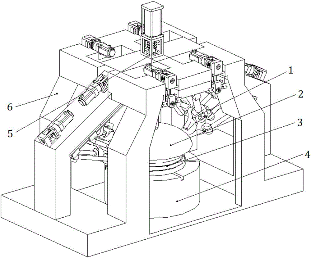
[0026] like figure 1 As shown, this embodiment includes: parts to be processed, oblique spinning mechanism 1, membrane 2, main shaft 3, controller 4, ejector pin 5 and fuselage shell 6, wherein: membrane 2, main shaft 3 and control The device 4 is sequentially connected and arranged in the fuselage shell 6, and the ejector rod 5 is arranged on the top of the fuselage shell 6 corresponding to the main shaft 3, and the parts to be processed are fixed on the tire membrane 2; the oblique spinning mechanism 1 It is symmetrically arranged on both sides of the ejector rod 5 and embedded with the fuselage shell 6; the controller 4 drives the oblique spinning mechanism 1 and drives the main shaft 3 to rotate.

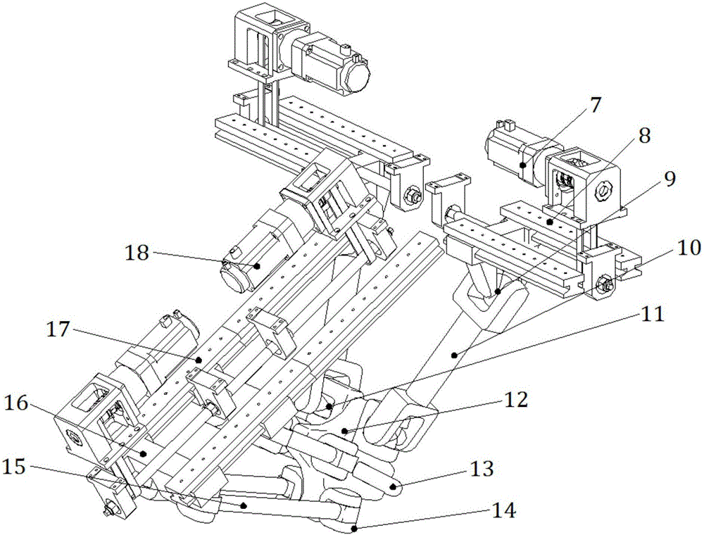
[0027] like figure 2 As shown, the oblique spinning mechanism 1 includes: a four-degree-of-freedom parallel robot, two lateral motors 7, two oblique motors 18, two parallel lateral screw guide rails 8 and two serial oblique wires rod guide rail 17, wherein: two horizontal scr...


PUM


Abstract

An upright spinning machine tool device with the spinning roller pose adjustable comprises oblique spinning mechanisms, a spindle, an ejector rod and a device body shell, wherein the spindle is arranged in the device body shell and right faces the ejector rod arranged on the upper portion of the device body shell, and the oblique spinning mechanisms are symmetrically arranged on the two sides of the ejector rod and embedded into the device body shell. Each oblique spinning mechanism comprises a four-freedom-degree parallel robot, two transverse motors, two oblique motors, two parallel transverse screw guide rails and two oblique screw guide rails, wherein the two oblique screw guide rails are coaxially arranged, the two transverse screw guide rails are coaxially arranged, and a T-shaped structure is formed by the oblique screw guide rails and the transverse screw guide rails; and the four-freedom-degree parallel robot is connected with the two transverse screw guide rails and the two oblique screw guide rails, and the transverse motors and the oblique motors are arranged on the transverse screw guide rails and the oblique screw guide rails correspondingly and drive the four-freedom-degree parallel robot to move. The upright spinning machine tool device is reasonable in design, high in machining precision and wide in application range.

Description

technical field [0001] The invention relates to a technology in the field of non-cutting forming by stamping, spinning or deep drawing, in particular to a vertical spinning machine tool device with adjustable wheel position and posture. Background technique [0002] The metal spinning process is a technology in which the ingredients are rotated to make the stress point from point to surface, and at the same time, a certain pressure is given by a rolling tool in a certain direction, so that the metal material is deformed and flowed along this direction to form a shape. [0003] At present, the high-efficiency and high-precision machining of ultra-large-diameter thin-walled components is a key technology that urgently needs to be solved in my country's aerospace and other fields. However, as the size of the component increases, it is difficult to manufacture the component using the overall method, and only local manufacturing processes such as spinning can be used. In the cur...

Claims


Application Information

Patent Timeline
Patent Type & Authority Applications(China)
IPC IPC(8): B21D22/14
CPCB21D22/14
Inventor 王皓赵龙海陈根良张壮赵亦希于忠奇
Owner SHANGHAI JIAO TONG UNIV
Why Eureka
Try Eureka