Fixture for machining engine cylinder end surface and crankshaft hole

A technology for engine cylinder block and crankshaft hole, which is applied in the direction of manufacturing tools, metal processing equipment, metal processing machinery parts, etc. Compact clamping effect

Inactive Publication Date: 2016-11-16
芜湖智高汽车部件有限公司
View PDF10 Cites 0 Cited by
  • Summary
  • Abstract
  • Description
  • Claims
  • Application Information

AI Technical Summary

Problems solved by technology

[0007] In order to solve the above-mentioned technical problems, the present invention provides a fixture for processing the end face of the engine cylinder block and the crankshaft hole, so as to solve the problems of low clamping efficiency and large space occupation, so that the processing of the entire cylinder block only uses two machining centers. Can complete the machining of the entire engine block

Method used


Image

  • Fixture for machining engine cylinder end surface and crankshaft hole
  • Fixture for machining engine cylinder end surface and crankshaft hole
  • Fixture for machining engine cylinder end surface and crankshaft hole

Examples


Embodiment Construction

[0025] The structural features of the present invention will now be described in detail in conjunction with the accompanying drawings.

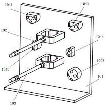
[0026] see figure 1 , 2 And 3, a fixture for engine block end face and crankshaft hole machining, including a tie rod assembly, a pressing plate assembly, and a support frame assembly.

[0027] see Figure 4 , 5 and 6, the rod assembly includes a base 101, an upper support rod 102, a lower support rod 103, and a positioning mechanism. Wherein, the base 101 is composed of vertical plates and horizontal plates, and is L-shaped. The vertical plate and the horizontal plate of the base 101 are at 90° to each other.

[0028] On the vertical plate of the base 101, an upper support rod 102, a lower support rod 103 and a positioning mechanism are arranged. The positioning mechanism is a block. The length of the upper support rod 102 is between 200mm and 700mm. The length of the lower support rod 103 is between 200mm and 700mm. Nuts are all eq...


PUM


Abstract

The invention provides a fixture for machining an engine cylinder end surface and a crankshaft hole. The fixture comprises a pull rod module, a pressing plate module and a support frame module; the pull rod module includes a base, an upper support rod, a lower support rod and a positioning mechanism; the pressing plate module is a rectangular block body; a special-shaped hole and a pressing point are arranged on the pressing plate module; and the support frame module includes a support base, a support column and a support body. The fixture has the following technical effects: after the fixture is used, the problems of low clamping efficiency and large occupied space can be solved, so that the machining of a whole engine cylinder can be finished by using two machining centers.

Description

technical field [0001] The invention belongs to the technical field of machining jigs for engine cylinder blocks, in particular to the machining of engine cylinder end faces and crankshaft holes, in particular to a jig for machining engine cylinder end faces and crankshaft holes. Background technique [0002] The cylinder block is one of the five core components of the automobile engine. Its processing technology has always been the key and difficult point in the production of the engine. Clamp from the outside, then press the cylinder body tightly with two round hole pressure plates, and then tighten the two nuts clockwise with a wrench to completely fix the cylinder body, there are many problems: [0003] 1. It is time-consuming and labor-intensive to clamp the car engine; [0004] 2. When the pressure plate is used to compress and fix the outside of the cylinder block of the automobile engine, the remaining space outside the cylinder block of the automobile engine is sma...

Claims


Application Information

Patent Timeline
IPC IPC(8): B23Q3/06
CPCB23Q3/062
Inventor 何继长朱培裴九芳
Owner 芜湖智高汽车部件有限公司
Why Eureka
Try Eureka