
Plastic coating device for large-diameter steel pipe

A large-diameter, steel pipe technology, applied in the field of large-diameter steel pipe plastic coating equipment, can solve problems such as long time spent, and achieve the effects of easy repair, small contact area, and small damage

Active Publication Date: 2016-11-16
高密天一机械科技有限公司
View PDF7 Cites 3 Cited by
  • Summary
  • Abstract
  • Description
  • Claims
  • Application Information

AI Technical Summary

Problems solved by technology

When using this production line to plastic-coat the steel pipe inside and outside, the inner coating process and the outer coating process of the steel pipe need to be carried out successively, so it takes a long time

Method used


Image

  • Plastic coating device for large-diameter steel pipe
  • Plastic coating device for large-diameter steel pipe
  • Plastic coating device for large-diameter steel pipe

Examples


Embodiment 1

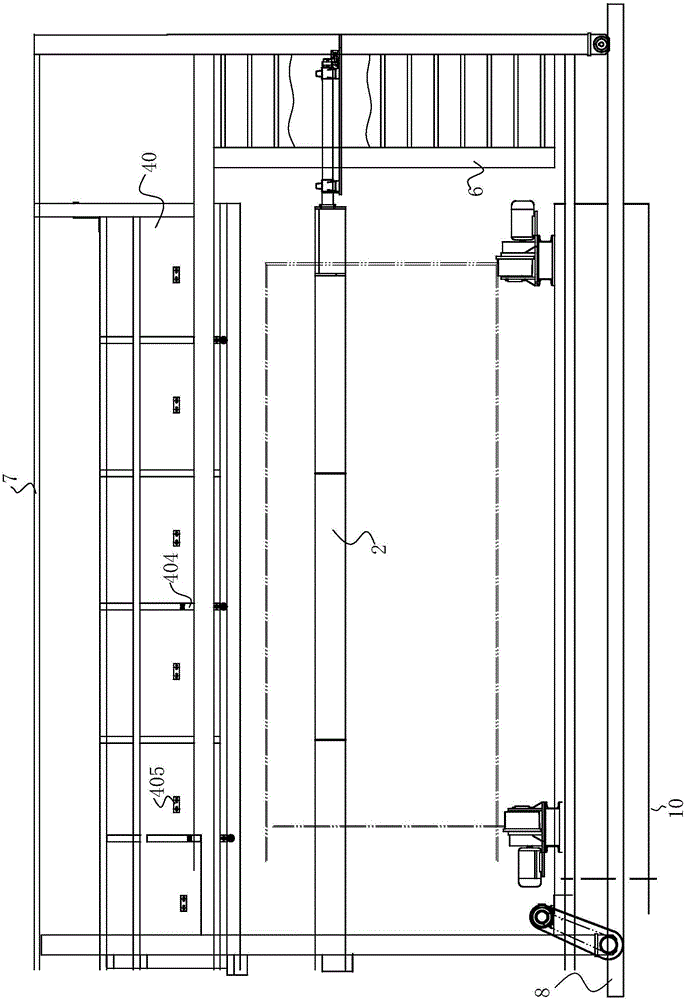
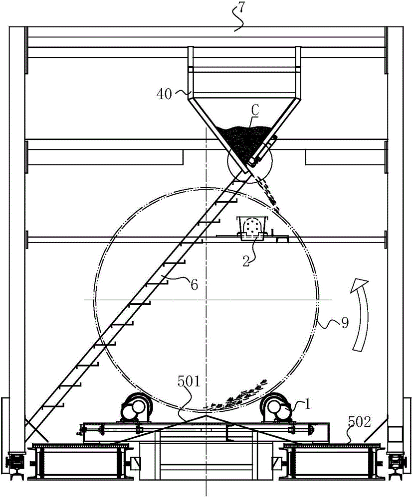
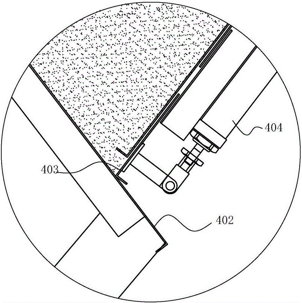
[0035] combine figure 1 , figure 2 , Figure 6 as well as Figure 7 As shown, a large-diameter steel pipe plastic coating equipment includes an underframe 10, and the underframe 10 is provided with a steel pipe rotating device 1. The steel pipe rotating device 1 is provided with two groups for supporting the two ends of the steel pipe 9 . Each group of steel pipe rotating device 1 includes a support base 105, which is installed on the chassis 10, and the support base 105 is rotatably equipped with at least two rollers 103 arranged side by side, and at least one roller 103 is a driving roller driven by a motor 104. In this embodiment, there are two rollers 103, both of which are driving rollers. The dual-drive mode can effectively avoid the slipping phenomenon between the steel pipe 9 and the rollers 103 during the plastic coating process.

[0036] Anti-slip teeth 109 are provided on the outer peripheral surface of the roller 103, and grooves for accommodating plastic powd...

Embodiment 2

[0050] combine Figure 8 and Figure 9 Commonly shown, two walking frames 7 are arranged on the same guide rail 8, the side of the two walking frames 7 close to each other is the inner side, and the side far away from the other is the outer side, and the inner plastic coating device installed on the two walking frames 7 The overturn driving mechanism of 2 is arranged on the outside of corresponding walking frame 7 respectively. The two walking frames 7 move toward each other along the track 8, and the powder chute 40 and the turning bucket 22 of the two walking frames 7 move from the two ends of the steel pipe to the middle position of the steel pipe. The combination of the inside and outside plastic coating devices on the two walking frames 7 can complete the inside and outside plastic coating to a long steel pipe 9 .


PUM


Abstract

The invention discloses a plastic coating device for a large-diameter steel pipe. The plastic coating device for the large-diameter steel pipe comprises a base frame. The base frame is provided with steel pipe rotating devices. A guide rail is arranged and parallel to the rotation axis of the steel pipe borne by the steel pipe rotating devices. Walking frames driven by a power device are arranged on the guide rail. The walking frame is provided with external plastic coating device bodies and internal plastic coating device bodies. Each internal plastic coating device body is located below the corresponding external plastic coating device body. Each external plastic coating device body comprises a powder material groove. The powder material grooves are fixed to the walking frames. Valve plates driven by the power device are arranged at feeding openings of the powder material grooves. Each internal plastic coating device body comprises a material overturning shaft. The material overturning shafts are rotationally installed on the walking frames. One end of each material overturning shaft is connected with an overturning drive mechanism. The other ends of the material overturning shafts are fixedly connected with material overturning hoppers capable of axially extending into the steel pipe. The plastic coating device can conduct internal plastic coating and external plastic coating on the large-diameter steel pipe at the same time and is high in coating speed, the coatings on the steel pipe are uniform, and the powder recovery rate is high.

Description

technical field [0001] The invention relates to the technical field of plastic-coating equipment for large-diameter steel pipes, in particular to plastic-coating equipment for large-diameter steel pipes. Background technique [0002] The inner and outer plastic-coated steel pipes are made by melting a layer of polyethylene (PE) resin, ethylene-acrylic acid copolymer (EAA), epoxy (EP) powder, non-toxic polypropylene (PP) or non-toxic polyvinyl chloride (PVC) on the steel pipe wall. ) and other organic substances, the plastic-coated steel pipe not only has the advantages of high strength, easy connection, water impact resistance, etc., but also overcomes the corrosion, pollution, scaling and low strength of the plastic pipe , poor fire performance and other shortcomings. [0003] Large-diameter steel pipes generally refer to steel pipes with a nozzle diameter of 300mm to 2400mm, which can be coated with plastic coatings with different properties such as polyvinyl chloride (PV...

Claims


Application Information

Patent Timeline
IPC IPC(8): B29C41/20B29C41/34B29C41/36B29L23/00
CPCB29C41/20B29C41/34B29C41/36B29L2023/22
Inventor 罗峰何相友邓志昌罗旭成
Owner 高密天一机械科技有限公司
Learn More