Flushing device for mechanical seal of centrifugal pump
A technology of mechanical seals and flushing devices, which is applied to mechanical equipment, parts of pumping devices for elastic fluids, pumps, etc., can solve the problems of mechanical seal residue, accumulation of impurities, and aggravated mechanical seals, so as to improve the sealing effect, The effect of preventing the deposition of particulate impurities and ensuring normal and stable operation
- Summary
- Abstract
- Description
- Claims
- Application Information
AI Technical Summary
Problems solved by technology
Method used
Image


Examples
Embodiment 1
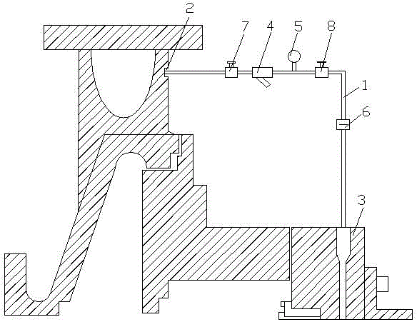
[0042] see figure 1 , a centrifugal pump mechanical seal flushing device, comprising a flushing pipe 1 connected to the centrifugal pump, the liquid inlet end of the flushing pipe 1 is connected to the outlet port 2 of the centrifugal pump, the liquid outlet end of the flushing pipe 1 is connected to the mechanical seal of the centrifugal pump 3 connection, the flushing pipe 1 is connected with a tubular filter 4, a pressure gauge 5 and a throttling orifice 6, the tubular filter 4 is close to the outlet end 2 of the centrifugal pump, and the throttling orifice 6 is close to The mechanical seal 3 of the centrifugal pump, the flushing pipe 1 is provided with a first shut-off valve 7 and a second shut-off valve 8, the first shut-off valve 7 is located between the outlet port 2 of the centrifugal pump and the tubular filter 4, The second stop valve 8 is located between the pressure gauge 5 and the throttle orifice 6 .
[0043] This embodiment is the most basic implementation mode...
Embodiment 2
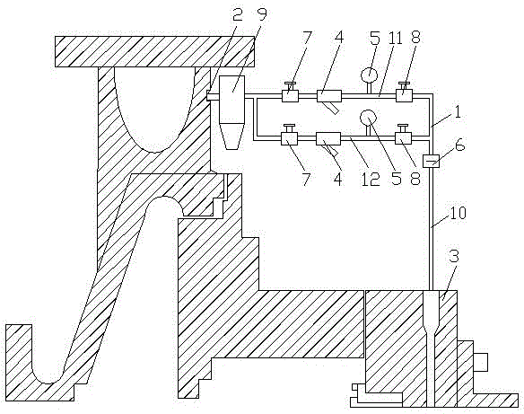
[0045] see figure 2 , a centrifugal pump mechanical seal flushing device, comprising a flushing pipe 1 connected to the centrifugal pump, the liquid inlet end of the flushing pipe 1 is connected to the outlet port 2 of the centrifugal pump, the liquid outlet end of the flushing pipe 1 is connected to the mechanical seal of the centrifugal pump 3 connection, the flushing pipe 1 is connected with a tubular filter 4, a pressure gauge 5 and a throttling orifice 6, the tubular filter 4 is close to the outlet end 2 of the centrifugal pump, and the throttling orifice 6 is close to The mechanical seal 3 of the centrifugal pump, the flushing pipe 1 is provided with a first shut-off valve 7 and a second shut-off valve 8, the first shut-off valve 7 is located between the outlet port 2 of the centrifugal pump and the tubular filter 4, The second stop valve 8 is located between the pressure gauge 5 and the throttle orifice 6 .
[0046] A suspension separator 9 is also included, one end o...
Embodiment 3
[0050] see image 3 , a centrifugal pump mechanical seal flushing device, comprising a flushing pipe 1 connected to the centrifugal pump, the liquid inlet end of the flushing pipe 1 is connected to the outlet port 2 of the centrifugal pump, the liquid outlet end of the flushing pipe 1 is connected to the mechanical seal of the centrifugal pump 3 connection, the flushing pipe 1 is connected with a tubular filter 4, a pressure gauge 5 and a throttling orifice 6, the tubular filter 4 is close to the outlet end 2 of the centrifugal pump, and the throttling orifice 6 is close to The mechanical seal 3 of the centrifugal pump, the flushing pipe 1 is provided with a first shut-off valve 7 and a second shut-off valve 8, the first shut-off valve 7 is located between the outlet port 2 of the centrifugal pump and the tubular filter 4, The second stop valve 8 is located between the pressure gauge 5 and the throttle orifice 6 .
[0051] A suspension separator 9 is also included, one end of...
PUM
 Abstract
Description
Claims
Application Information