Coordinate transfer method for shaft excavation construction

A technology of shafts and coordinates, which is used in measuring devices, instruments, surveying and mapping, and navigation, etc., can solve problems such as the inability to solve the problems of accurate steering in the downward bending plane of the shaft, the wire is easily broken, and the safety risk is high, so as to improve the construction efficiency and improve the safety. Construction efficiency, the effect of simplifying construction steps

Inactive Publication Date: 2016-11-16
CHINA GEZHOUBA GRP SURVEY DESIGN CO LTD
View PDF6 Cites 6 Cited by
  • Summary
  • Abstract
  • Description
  • Claims
  • Application Information

AI Technical Summary

Problems solved by technology

[0002] During the shaft construction process, the shaft measurement method is mostly to hang the steel wire at the center of the top of the shaft, hang the plumb or install the laser guide, measure the distance from the laser emitted by the steel wire or the laser guide to the side line of the shaft excavation and draw it. line, as the outline of the construction excavation, but the method of hanging the steel wire at the center of the top of the shaft has the problem that the steel wire needs to be frequently retracted and retracted due to the blasting of the shaft, and the steel wire is easily broken during the blasting operation of the shaft excavation, or the working crane suspended from the top of the shaft Basket winding and other problems; the method of installing a laser guide at the center of the top of the shaft has vibration due to the excavation of the shaft, and the laser guide installed on the top of the shaft needs to be frequently adjusted. The deeper the shaft is excavated, the laser is adjusted at the top of the shaft every time. The greater the safety risk of the guide device
And adopting above-mentioned two kinds of methods all can't solve the planar accurate steering of shaft downward bending

Method used


Image

  • Coordinate transfer method for shaft excavation construction

Examples


Embodiment 1

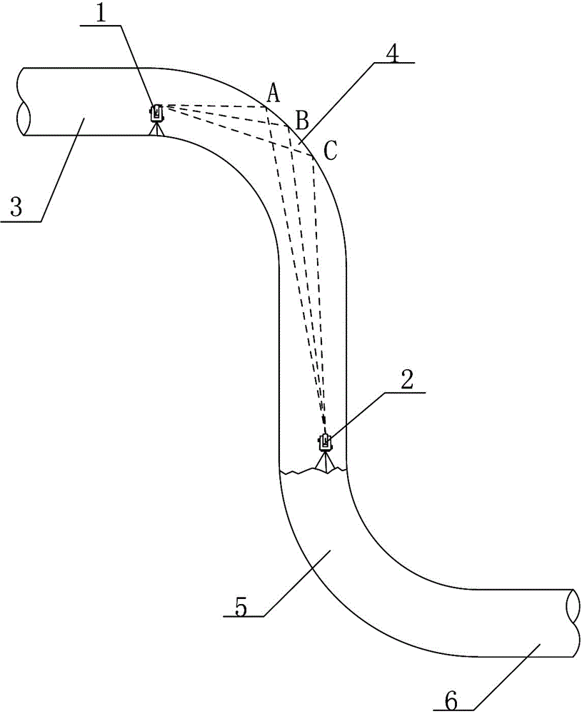
[0019] A coordinate transfer method for shaft excavation construction, comprising a first total station 1 and a second total station 2, the first total station 1 is set up on the upper flat section 3 of the shaft, and the second total station is set up at the bottom of the shaft The station instrument 2 detects the coordinates of the laser point projected on the upper curve section 4 through the first total station instrument 1, and sets the second total station instrument 2 to realize coordinate transfer.

Embodiment 2

[0021] On the basis of embodiment 1, comprise the following steps:

[0022] 1) Set up the first total station 1 and the second total station 2 on the upper flat section 3 and the bottom of the shaft respectively;

[0023] 2) Use the second total station 2 at the bottom of the shaft to project the laser on the point A on the upward curved section 4, and then use the first total station 1 installed on the upper flat section 3 to project the laser, so that the first total station 1 The laser is projected on point A, and the coordinate value of point A is obtained;

[0024] 3) Use the second total station 2 at the bottom of the shaft to project the laser on the point B on the upward curved section 4, and then use the first total station 1 installed on the upper flat section 3 to project the laser, so that the first total station 1 The laser is projected on point B, and the coordinate value of point B is obtained;

[0025] 4) According to the coordinates of the two points in step...


PUM


Abstract

A coordinate transfer method for shaft excavation construction is provided. A first total station and a second total station are included; the first total station is set up on the upper horizontal section of the shaft; the second total station is set up on the bottom of the shaft; the first total station detects the laser point coordinates projected on an upper bending section, so as to set up the second total station and realize coordinate transfer. The method includes the following steps: 1) respectively setting up the first total station and the second total station on the on upper horizontal section and the bottom of the shaft; 2) acquiring the coordinate of a point A; 3) acquiring the coordinates of a point B; 4) setting the second total station according to the coordinates of the two points in the steps A and B; 5) comparing the coordinate of a point C measured by the first total station and second total station, and controlling the error in an allowable range, so as to complete coordinate transfer; and 6) carrying out lofting of a shaft excavation contour line, overexcavation and underbreak inspection, fracture surface measurement by using the CASIO calculator program to complete turning determination of a lower horizontal section.

Description

technical field [0001] The invention relates to the technical field of shaft construction, in particular to a coordinate transfer method for shaft excavation construction. Background technique [0002] During the shaft construction process, the shaft measurement method is mostly to hang the steel wire at the center of the top of the shaft, hang the plumb or install the laser guide, measure the distance from the laser emitted by the steel wire or the laser guide to the side line of the shaft excavation and draw it. line, as the outline of the construction excavation, but the method of hanging the steel wire at the center of the top of the shaft has the problem that the steel wire needs to be frequently retracted and retracted due to the blasting of the shaft, and the steel wire is easily broken during the blasting operation of the shaft excavation, or the working crane suspended from the top of the shaft Basket winding and other problems; the method of installing a laser guid...

Claims


Application Information

Patent Timeline
Patent Type & Authority Applications(China)
IPC IPC(8): G01C15/00G01C7/06
CPCG01C7/06G01C15/00
Inventor 范学振邱章云唐亿阶晏春波胡天祥罗琛
Owner CHINA GEZHOUBA GRP SURVEY DESIGN CO LTD
Why Eureka
Try Eureka