
Drilling rod with axial deep groove wear-resistant joint for well drilling

A deep groove, axial technology, applied in the direction of drill pipe, drilling equipment, drill pipe, etc., can solve the problems of increasing mud circulation loss along the way, not solving fundamental problems, increasing circulating pump pressure, etc., to reduce the labor force of workers Labor intensity, reduce the labor intensity of workers, and promote the effect of circulation

Active Publication Date: 2021-01-22
JILIN UNIV
View PDF7 Cites 2 Cited by
  • Summary
  • Abstract
  • Description
  • Claims
  • Application Information

AI Technical Summary

Problems solved by technology

At the same time, when the drill pipe enters the formation that is prone to shrinkage and mud bag, it is easy to happen that the well diameter is close to the drill pipe joint, resulting in downhole accidents such as holding the pump or sticking the drill pipe.
In addition, the mud circulation channel between the well wall and the joint is small, which increases the loss along the mud circulation and leads to an increase in the circulating pump pressure
[0004] In order to improve the wear resistance of joints, professional technicians have developed welded wear-resistant strips without hard particles such as tungsten carbide. Although it has played a great role, it has not solved the fundamental problem.

Method used


Image

  • Drilling rod with axial deep groove wear-resistant joint for well drilling
  • Drilling rod with axial deep groove wear-resistant joint for well drilling
  • Drilling rod with axial deep groove wear-resistant joint for well drilling

Examples


Embodiment Construction

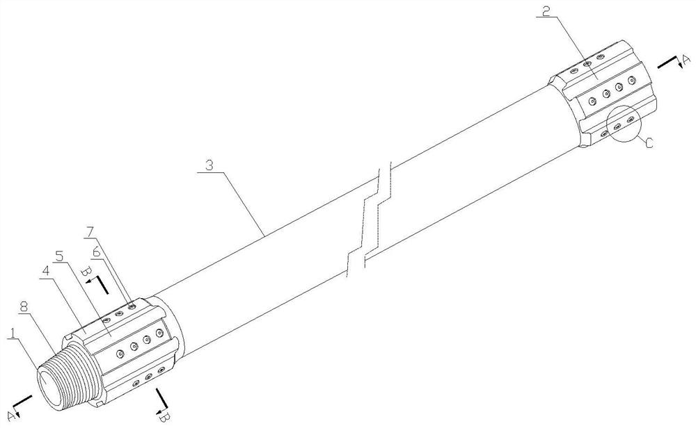
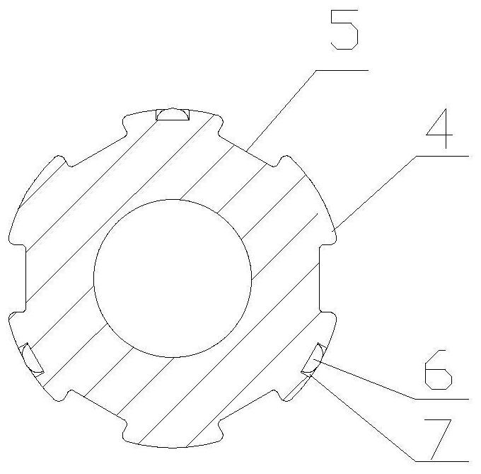
[0017] A drill pipe for drilling with axial deep groove wear-resistant joints, including a rod body 3, and the axial ends of the rod body 3 are respectively provided with a male joint 1 and a female joint 2 with a diameter larger than the rod body 3 (consistent with the national standard for drill pipes) , the bottom of the male joint 1 is provided with a male joint connecting part 8 with an external thread, and the inside of the female joint 2 is provided with an internal thread 9 matching with the male joint connecting part 8, and the male joint 1 and the female joint 2 have a plurality of Joint unscrewing slots 5 extending along its axial direction, joint anti-wear ribs 4 are formed between two adjacent joint unscrew slots 5, and joint anti-wear ribs 4 are provided with wear-resistant materials or provided with multiple Convex crown installation blind hole 7, smooth and wear-resistant convex crown 6 is fixedly connected in the convex ball installation blind hole 7, the highe...


PUM


Abstract

The invention relates to the technical field of drilling in geological engineering, in particular to a drilling rod with an axial deep groove wear-resistant joint for well drilling. The drilling rod comprises a rod body, a male connector and a female connector are arranged at two ends of the rod body, and a plurality of connector unscrewing clamping grooves extending along the axial direction of the male connector and the female connector are distributed on the male connector and the female connector in the circumferential direction. A connector anti-abrasion flange is formed between every twoadjacent connector screwing and unscrewing clamping grooves and provided with wear-resistant materials or a plurality of convex spherical crown installation blind holes, the smooth wear-resistant convex spherical crowns are fixedly connected into the convex spherical crown installation blind holes, and the rod body, the male connector and the female connector are each of a through hollow structure. The drill rod can be continuously screwed or unscrewed without applying radial pressure in the tripping and drill rod screwing and unscrewing processes, no damage is caused to the surface of the connector, abrasion of the connector is only generated in a well and the wall of the well, and therefore the overall service life of the drill rod is prolonged, the probability of accidents such as drilling tools and jamming of the drill rod is reduced, and the safety of the drill rod is improved. Therefore, the working efficiency of drilling is improved and the drilling cost is saved.

Description

technical field [0001] The invention relates to the technical field of drilling, in particular to a drill pipe for drilling with an axial deep groove wear-resistant joint. [0002] technical background [0003] At present, drill pipe is one of the necessary downhole tools for drilling technology, and its role is very important. The drill pipe structure is mainly composed of male and female joints and the main body. The function of the joint is to connect the drill pipes to form a long drill string. Usually, the outer diameter of the joint is larger than that of the main body. The joint is the main part clamped by the unscrewing tool. However, the jig of the unscrewing tool needs to generate enough friction with the outer surface of the joint through a huge clamping force to unscrew or unscrew the joint between the drill pipes. At this time, the jaws It has been deeply embedded into the outer surface of the joint and under the action of torsion, long circumferential scratches...

Claims


Application Information

Patent Timeline
Patent Type & Authority Applications(China)
IPC IPC(8): E21B17/042E21B17/10E21B17/00
CPCE21B17/042E21B17/1085E21B17/00
Inventor 赵研张丛珊高科李家晟
Owner JILIN UNIV
Learn More