Eureka AIR delivers breakthrough ideas for toughest innovation challenges, trusted by R&D personnel around the world.

Full-automatic current comparator high-voltage bridge based on FPGA and voltage control current source

A technology of voltage-controlled current and current ratio, which is applied in the direction of AC/DC measuring bridge, measuring resistance/reactance/impedance, instruments, etc., which can solve the problem that high-precision measurement and automatic measurement cannot be realized at the same time, and the operator has high technical requirements , limited measurement accuracy and other issues, to achieve high real-time and certainty, to achieve the effect of fully automated, high-precision measurement

Active Publication Date: 2016-11-16
HARBIN UNIV OF SCI & TECH
View PDF3 Cites 4 Cited by
  • Summary
  • Abstract
  • Description
  • Claims
  • Application Information

AI Technical Summary

Problems solved by technology

This method realizes automatic measurement, but the extracted voltage signal and current signal belong to direct measurement, there is no definite benchmark, and the measurement accuracy is very limited
[0006] In summary, no matter the existing bridge method or the phase comparison method, they either have low precision, or require manual operation and have high technical requirements for operators, and cannot simultaneously achieve high-precision measurement and automatic measurement

Method used


Image

  • Full-automatic current comparator high-voltage bridge based on FPGA and voltage control current source
  • Full-automatic current comparator high-voltage bridge based on FPGA and voltage control current source
  • Full-automatic current comparator high-voltage bridge based on FPGA and voltage control current source

Examples


Embodiment Construction

[0030] Exemplary embodiments of the present invention will be described below with reference to the accompanying drawings. In the interest of clarity and conciseness, not all features of an actual implementation are described in this specification. It should be understood, however, that in developing any such practical embodiment, many implementation-specific decisions must be made in order to achieve the developer's specific goals, such as meeting those constraints related to the system and business, and those Restrictions may vary from implementation to implementation. Moreover, it should also be understood that development work, while potentially complex and time-consuming, would at least be a routine undertaking for those skilled in the art having the benefit of this disclosure.

[0031] Here, it should also be noted that, in order to avoid obscuring the present invention due to unnecessary details, only the device structure and / or processing steps closely related to the ...


PUM


Abstract

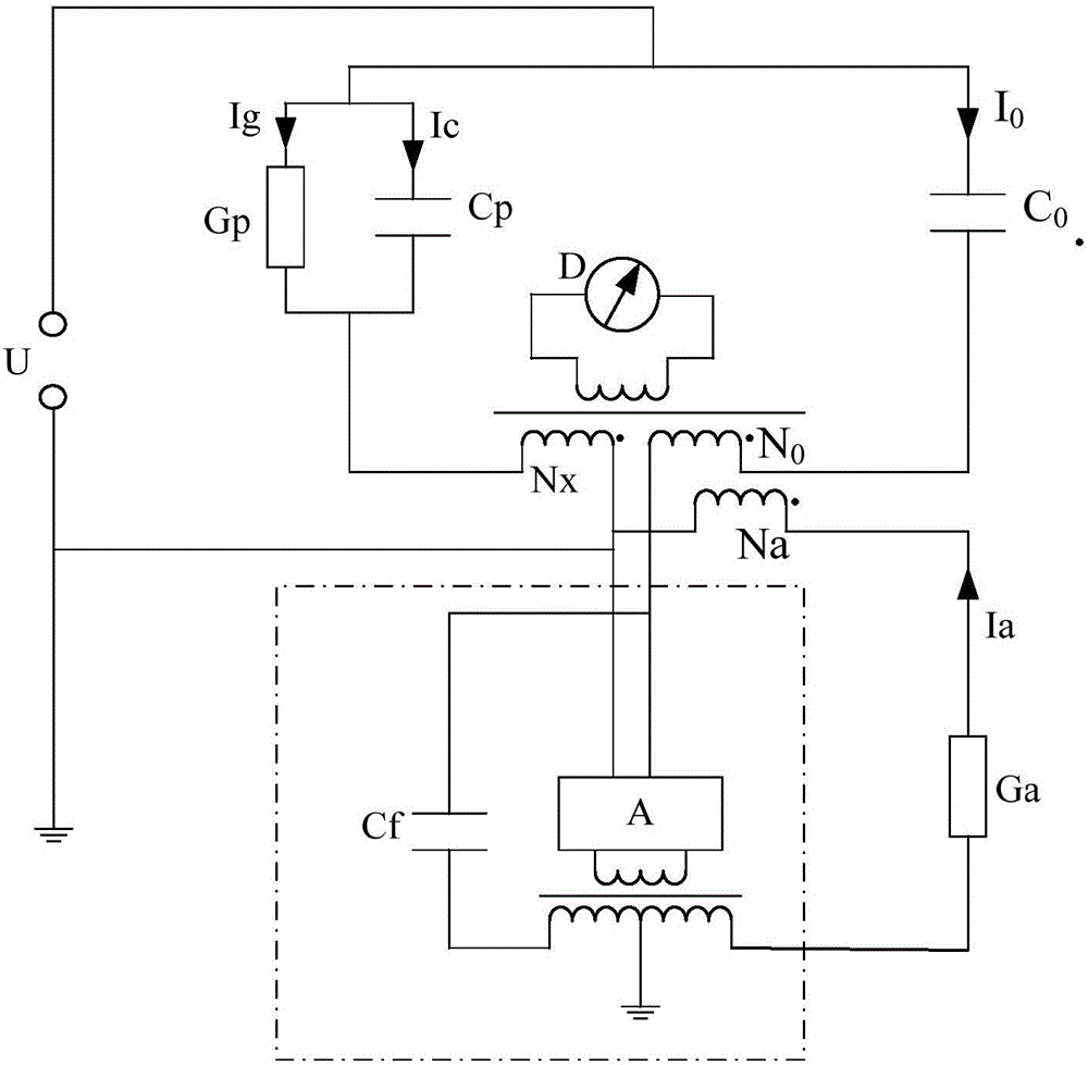
The invention provides a full-automatic current comparator based on an FPGA and a voltage control current source. The full-automatic current comparator high-voltage bridge comprises the components of a voltage divider, a high-voltage power supply, the FPGA, a first analog input module, a second analog input module, an RT, an industrial personal computer, a voltage control current source, an analog output module, a programmable amplifier, a current comparator and a tested sample. The current comparator comprises a testing coil, a first proportional coil and a second proportional coil. The testing coil and the programmable amplifier are used for testing the balance degree of the current comparator. The two proportional coils with fixed numbers of coils are respectively connected with the tested sample and the voltage control current source. Comparative current measurement of the sample current is realized according to an ampere turns balance principle. The full-automatic current comparator high-voltage bridge based on the FPGA and the voltage control current source can realize measurement on capacitance and loss factor of a capacitive tested sample and measurement on inductance and quality factor of an inductive tested sample in a high-voltage condition.

Description

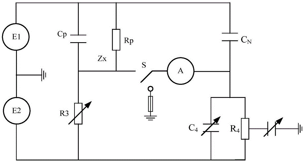
technical field [0001] The invention relates to electrical measurement technology, in particular to a full-automatic current ratio high voltage bridge based on FPGA and voltage control current source. Background technique [0002] Under high voltage conditions, the capacitance value and loss factor of capacitive test products are mostly measured by the bridge method, and the main equipment is a high-voltage Xilin bridge and a high-voltage current ratio bridge. [0003] The high-voltage Xilin bridge is the most traditional equipment for measuring the capacitance value and loss factor of capacitive samples. Its working principle is as follows: Figure 1A shown. Specifically, the test sample is equivalent to a complex impedance and compared with a standard capacitor, and the standard resistor R3 and capacitor C4 of the proportional arm on the low-voltage side are adjusted to meet the equal product of the impedance on the opposite side to achieve bridge balance, and then calcula...

Claims


Application Information

Patent Timeline
IPC IPC(8): G01R17/12G01R27/26
CPCG01R17/12G01R27/26
Inventor 李忠华董旭
Owner HARBIN UNIV OF SCI & TECH
Why Eureka
Eureka Blog
Learn More