Clutch system with dual clutch and CSC with an axial CSC bearing comprising a platform for receiving the CSC, and powertrain

A power train and clutch technology, applied in the field of clutch systems, can solve problems such as separate structural space and achieve the effect of saving axial structural space

Inactive Publication Date: 2016-11-16
SCHAEFFLER TECH AG & CO KG
View PDF8 Cites 2 Cited by
  • Summary
  • Abstract
  • Description
  • Claims
  • Application Information

AI Technical Summary

Problems solved by technology

[0004] However, the embodiments known from the prior art are designed to be relatively large in particular in

Method used


Image

  • Clutch system with dual clutch and CSC with an axial CSC bearing comprising a platform for receiving the CSC, and powertrain

Examples


Embodiment Construction

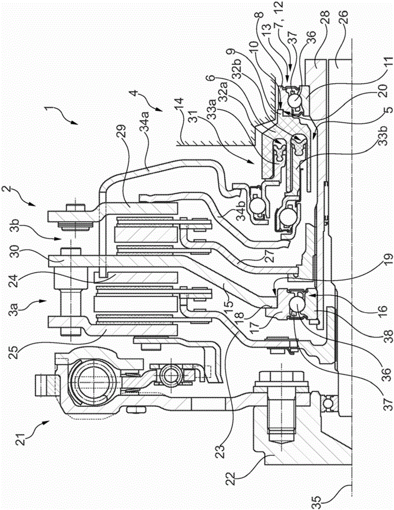
[0026] only figure 1 An advantageous embodiment of the clutch system 1 according to the invention is shown. In this figure, the clutch system 1 is shown already in a state in which the clutch system is integrated into the drive train of a motor vehicle. The clutch system 1 here includes a clutch 2 which is designed as a double clutch. Here, the clutch 2 is connected on the input side in a rotationally fixed manner to an output shaft 22 / crankshaft of an internal combustion engine, for example an Otto or Diesel engine, by means of a damping device 21 , which is designed here as a dual-mass flywheel. According to the design of the double clutch, the clutch 2 has two clutch parts / subclutches 3a and 3b, wherein the first clutch part is provided with the reference numeral 3a and the other second subclutch or another second clutch part is provided with the reference numeral 3b.

[0027] Each partial clutch / clutch part 3a and 3b is in turn designed as a dry friction clutch / frictio...


PUM


Abstract

The invention relates to a clutch system (1) for a powertrain of a motor vehicle, comprising a clutch (2), which has at least one sub-clutch (3a, 3b), and an actuating device (4), which is provided in order to move the at least one sub-clutch (3a, 3b) between an engaged and a disengaged position. The actuating device (4) has a cylinder housing (6) which forms a central passage opening (5) for passing a transmission input shaft (26, 28) and which is axially and/or radially mounted by means of a support bearing (7). A bearing ring (8) of the support bearing (7) has a recess (10) which at least partly receives an axially oriented extension (9) of the cylinder housing (6). The invention also relates to a powertrain for a motor vehicle, comprising a transmission housing (14), which has an opening (13), and a clutch system (1) of the type according to the invention, at least the support bearing (7) being arranged radially within the opening (13).

Description

technical field [0001] The invention relates to a clutch system for a drive train of a motor vehicle, such as a passenger car, truck, bus or agricultural truck, said clutch system having (at least one) clutch and an actuating device, said clutch having at least one A partial clutch, the actuating device is configured to adjust the at least one partial clutch between an engaged and a disengaged position, wherein the actuating device in turn has a cylinder housing which forms a central through-opening for Passing or inserting the transmission input shaft, the cylinder housing is axially (in the axial direction with respect to the rotational axis of the clutch) and / or radially (in the radial direction with respect to the rotational axis of the clutch) by means of support bearings direction) support / support. The sub-clutch is also referred to as a clutch section. Background technique [0002] Various clutch systems are known from the prior art, ie combinations of at least one ...

Claims


Application Information

Patent Timeline
IPC IPC(8): F16D25/10F16D21/06
CPCF16D13/385F16D13/70F16D21/06F16D25/10F16F15/121F16D2021/0669F16D2021/0615F16D2300/12F16D2250/0023F16D25/082F16D2021/0692F16D2021/0607F16D2300/22F16D13/72F16D2250/003
Inventor 迈克尔·鲍曼
Owner SCHAEFFLER TECH AG & CO KG
Why Eureka
Try Eureka