
Device for reinforcing loading capacity of joint robot and control method thereof

A technology of robots and joints, applied in the directions of manipulators, manufacturing tools, joints, etc., can solve problems such as damage to guide rails, rollover, etc., and achieve the effect of preventing the sudden change of the rotation axis and improving the towing capacity

Active Publication Date: 2016-11-23
宁夏巨能机器人股份有限公司
View PDF8 Cites 1 Cited by
  • Summary
  • Abstract
  • Description
  • Claims
  • Application Information

AI Technical Summary

Problems solved by technology

[0002] Joint robot, also known as joint arm robot or joint robot arm, is one of the most common forms of industrial robots in today's industrial field; it is suitable for mechanical automation operations in many industrial fields, such as automatic assembly, painting, handling and welding. ; According to the structure of joint robots, it is classified into five-axis and six-axis joint robots, pallet joint robots and planar joint robots. Programming can complete fully automated work, improve production efficiency, controllable error rate, and replace many complex tasks that are not suitable for manpower and harmful to health, such as spot welding of car shells; due to the complicated working environment of joint robots, Therefore, its load-bearing capacity is required to be relatively good. The load-bearing capacity of existing joint robots can only be adjusted as a whole by adjusting the strength of the power mechanism, but the whole machine needs to be modified, and it is easy to cause rollover or damage the guide rail.

Method used


Image

  • Device for reinforcing loading capacity of joint robot and control method thereof
  • Device for reinforcing loading capacity of joint robot and control method thereof

Examples


Embodiment Construction

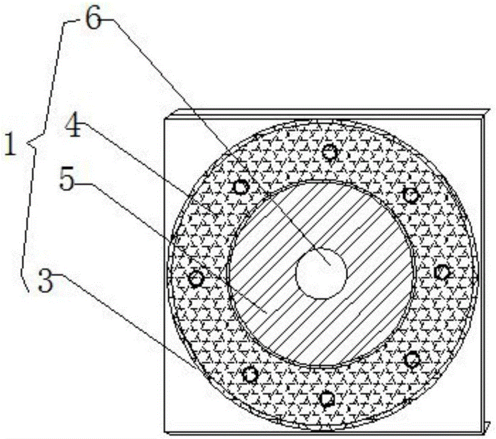
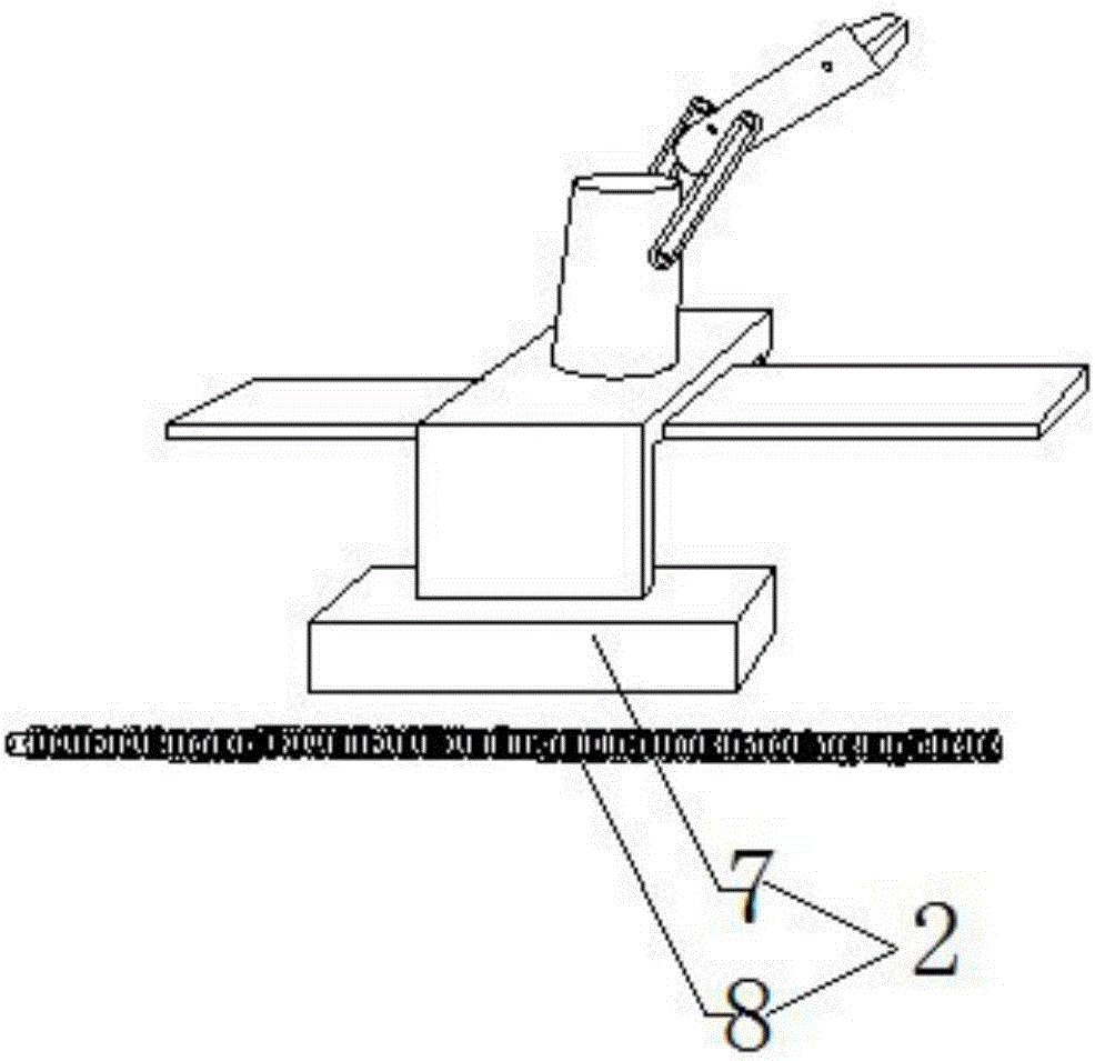
[0017] Such as figure 1 and figure 2 As shown, the present invention is used to enhance the load-bearing capacity of the joint robot, including the joint rotation axis load-bearing one-way motion device 1 and the load-bearing chassis counterweight device 2, and the joint rotation axis load-bearing one-way motion device 1 includes a joint rotation axis load-bearing one-way motion device 1 that is compatible with the joint robot rotation axis The internal gear part 3 installed on the outside, and the intermediate gear part 4 installed on the inside of the internal gear part with the joint robot rotating shaft, and the external gear part 5 arranged on the inside of the intermediate gear part; the outside of the intermediate gear part 4 and The inner sides are provided with meshing gear grooves (not shown); the external gear 5 is installed in cooperation with the driving motor 6; the load-bearing chassis counterweight device 2 includes a magnetic block 7 installed on one side of ...


PUM


Abstract

The invention discloses a device for reinforcing loading capacity of a joint robot. The device comprises a joint rotating shaft loading one-way moving device and a bearing chassis counterweight device; the joint rotating shaft loading one-way moving device includes an inner gear piece mounted on the outer side of a joint robot rotating shaft, a middle gear piece mounted with the joint robot rotating shaft and arranged on the inner side of the inner gear piece, and an outer gear piece arranged on the inner side of the middle gear piece; the outer gear piece is matched and mounted with a driving motor; the bearing chassis counterweight device includes a magnetic block mounted on one side of a bearing chassis; the magnetic block is parallel to a joint robot truss guide rail; and a powerful electromagnetic bar is arranged rightly below the magnetic block. The control method comprises the steps of: workpiece grabbing, balancing, lifting and emptying. The device for reinforcing loading capacity of the joint robot adopts a heightening accumulation mode to improve the drag loading capacity of a servo motor, and can balance the bearing chassis.

Description

technical field [0001] The invention relates to a joint robot, in particular to a device for enhancing the load-bearing capacity of a joint robot and a control method thereof, belonging to the technical field of joint robots. Background technique [0002] Joint robot, also known as joint arm robot or joint robot arm, is one of the most common forms of industrial robots in today's industrial field; it is suitable for mechanical automation operations in many industrial fields, such as automatic assembly, painting, handling and welding. ; According to the structure of joint robots, it is classified into five-axis and six-axis joint robots, pallet joint robots and planar joint robots. Programming can complete fully automated work, improve production efficiency, controllable error rate, and replace many complex tasks that are not suitable for manpower and harmful to health, such as spot welding of car shells; due to the complicated working environment of joint robots, Therefore,...

Claims


Application Information

Patent Timeline
IPC IPC(8): B25J17/00B25J13/00
Inventor 宋明安孙洁付焕清刘学平同彦恒李志博麻辉
Owner 宁夏巨能机器人股份有限公司
Learn More