Injection molding machine and injection screw thereof

A molding machine and screw technology, which is applied in the field of injection molding machine and its injection screw, can solve the problems of not being able to obtain excellent comprehensive performance, and achieve the effects of preventing uncontrolled temperature rise, high plasticizing efficiency, and low shear volume

Active Publication Date: 2016-11-23
震雄机械(深圳)有限公司
View PDF4 Cites 4 Cited by
  • Summary
  • Abstract
  • Description
  • Claims
  • Application Information

AI Technical Summary

Problems solved by technology

[0010] The present invention proposes an injection molding machine and its injection screw, which solves the problems of production efficiency, plasticizing effect and temperature in the prior art due to the traditional single-thread injection screw and several commo

Method used


Image

  • Injection molding machine and injection screw thereof
  • Injection molding machine and injection screw thereof
  • Injection molding machine and injection screw thereof

Examples


Embodiment Construction

[0038] In order to further illustrate the principle and structure of the present invention, preferred embodiments of the present invention will now be described in detail with reference to the accompanying drawings.

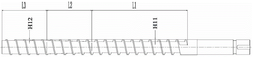
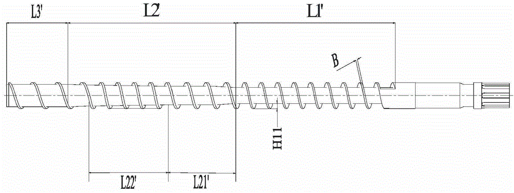
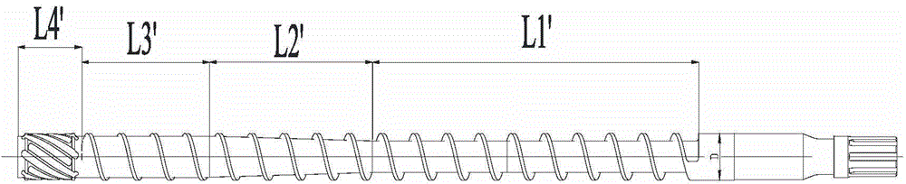
[0039] refer to Figure 7 to Figure 12 , the present invention provides an injection molding machine 100, which includes a plastic injection part 1, the plastic injection part 1 includes a barrel set 2, the barrel set 2 includes an injection screw 3, and the injection screw 3 is used to inject plastic Plasticized into a melt in the injection molding machine 100 . One end of the injection screw 3 is connected with the drive motor 8 through the transmission part 9, and the other end is equipped with three small parts of the check valve, which include the screw head 4, the non-return ring 5 and the thrust washer 6.

[0040] The injection screw 3 includes a threaded portion 31 and a coupling portion 32 connected to each other. The coupling part 32 includes a coupli...


PUM


Abstract

The invention provides an injection molding machine and an injection screw thereof. The screw thread part of the injection screw comprises a feeding section, a compressing section and a homogenizing section; the homogenizing section is formed by large-pitch spiral grooves and spiral wave crests; and a gap between the spiral wave crests and the inner wall of a charging barrel is small, and when a motor drives the screw to rotate to plastify raw materials, all sol needs to cross the gap to obtain suitable cutting. The plastified sol enters the large-pitch spiral grooves and is conveyed into the material storage space of the charging barrel at relatively small damping and high efficiency. When the sol enters the deeper spiral grooves after crossing the spiral wave crests, eddy currents are formed to generate scroll currents along the depth of the spiral grooves; uniform chaotic mixing is conducted on the plastified sol, and heat exchange between the sol and the charging barrel is conducted more fully; and a uniform-temperature sol body with high quality is generated. According to the injection molding machine and the injection screw thereof, the material is fully plastified at smaller cutting displacement and higher plastifying efficiency. The defects of uncontrolled temperature rising, slipping of the screw, slow feeding and the like which are prone to occur in the sol melting process are overcome.

Description

technical field [0001] The invention relates to molding equipment, in particular to an injection molding machine and its injection screw. Background technique [0002] At present, the commonly used injection screws are traditional three-stage single-flight screw, general-purpose variable-pitch screw, barrier-type high-mixing screw, and split-type double-flight screw. [0003] Such as figure 1 As shown, it is a traditional three-section single-flight screw. The three-section single-flight screw includes a threaded part and a connecting part, and the threaded part includes a feed section L1', a compression section L2' and a homogenization section L3'. The feeding section L1' is formed by the external threads with straight roots with a depth of H11, the compression section L2 is composed of external threads with inclined roots, and the homogenizing section L3' is composed of external threads with straight roots with a depth of H12. Its working principle is: the plastic raw m...

Claims


Application Information

Patent Timeline
IPC IPC(8): B29C45/60
Inventor 蒋志坚王海平
Owner 震雄机械(深圳)有限公司
Why Eureka
Try Eureka