
Manufacturing apparatus of slag ball

A technology for manufacturing devices and slag balls, applied in recycling technology and other directions, can solve the problems of wear resistance and strength decline, indoor temperature rise, and work site environment deterioration, etc., to improve strength and wear resistance, and reduce indoor temperature. , the effect of reducing the flying distance

Inactive Publication Date: 2016-11-23
田官钰
View PDF6 Cites 0 Cited by
  • Summary
  • Abstract
  • Description
  • Claims
  • Application Information

AI Technical Summary

Problems solved by technology

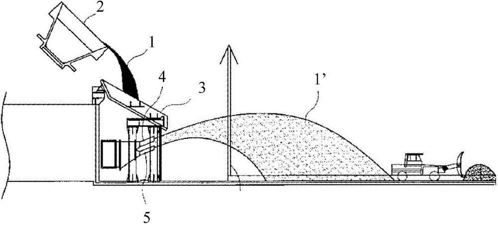
In addition, the molten slag 1 is slowly and continuously cooled through the long funnel 3, so there is a concern that the wear resistance and strength of the slag ball 1' will decrease.
[0009] In addition, in the prior art described above, the slag 1 is pulverized and cooled by the blowers 4 and 5, but the effect of lowering the temperature of the slag 1 may not be significant only by the gas supplied from the blowers 4 and 5. , resulting in poor particle size of the slag ball 1', and the agglomeration phenomenon caused by the solidification of the slag 1
[0010] In addition, in the prior art described above, by supplying gas to the lower portion of the slag 1 falling from the hopper 3, the pulverized slag balls 1' are scattered to the upper portion forward.
However, in this case, since the moving radius of the falling slag ball 1' is long, the scale of the required work site needs to be more than necessary, and there is a possibility that the temperature in the room may rise, and there is a possibility that the work will be damaged due to excessive dust. Disadvantages of poor environment on site

Method used


Image

  • Manufacturing apparatus of slag ball
  • Manufacturing apparatus of slag ball
  • Manufacturing apparatus of slag ball

Examples


Embodiment Construction

[0043] Hereinafter, embodiments of the present invention will be described in detail with reference to the drawings. However, in describing the present invention, when the technical idea of ​​the present invention is obscured or unclear by concretely describing a known structure, the description of the above-mentioned known structure will be omitted.

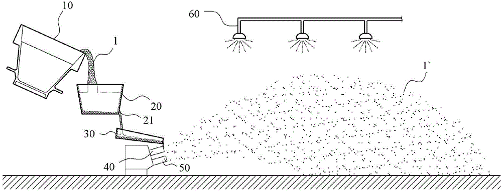
[0044] figure 2 It is a figure which shows the shot manufacturing apparatus of this invention.

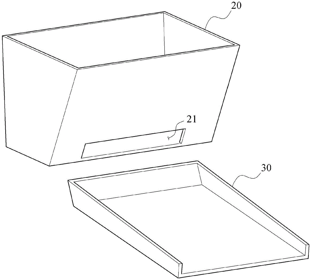
[0045] Such as figure 2 As shown, the slag ball manufacturing device of the present invention is characterized in that it includes: a slag tank 10 for discharging slag 1; A discharge hole 21 for discharging temporarily stored molten slag 1 is formed on the lower side of the front; a drain member 30 transfers the molten slag 1 discharged from the discharge hole 21 of the above-mentioned slag hopper 20; and a blower 40 is located at the end of the above-mentioned drain member 30 In the lower part of the slag 1 , the molten slag 1 ...


PUM


Abstract

The invention relates to manufacturing apparatus of a slag ball. The spherical slag ball is manufactured through quick chilling and flying of molten slag in a molten state in a slag tank to be reutilized for industrial use. The manufacturing apparatus of the slag ball is characterized by comprising the slag tank, a slag hopper, a drainage piece and an air blower, wherein the molten slag is discharged out of the slag tank; the slag hopper is used for temporally storing the molten slag discharged out of the slag tank; discharging holes for discharging the temporally-stored molten slag are formedin the lower side of the front portion of the slag hopper; the drainage piece is used for moving the molten slag discharged out of the discharging holes of the slag hopper; and the air blower is located on the lower portion of the tail end of the drainage piece, so that the molten slag which is moved through the drainage piece and falls off is cooled and flies to be granulated, and the slag ballis manufactured.

Description

technical field [0001] The present invention relates to a slag ball manufacturing apparatus (Manufacturing apparatus of slag ball) for rapidly cooling and scattering molten slag in a slag pot to manufacture spherical slag balls and reuse them for industrial use. Background technique [0002] The steel slag produced in the electric furnace or converter process is usually packed in the slag tank and poured into the open storage yard. If the steel slag solidifies, it is put into the crusher equipment. At this time, the iron (Fe) oxide contained in the steel slag is screened and separated by a magnet, and reused as an iron raw material for steelmaking, and the solidified pure steel slag is usually granulated in the form of an aggregate of 40 mm or less, and used as It can be reused as road paving material (Korean Patent Publication No. 10-1175479). [0003] On the other hand, as a conventional technology, in the patent publication No. 10-1194277 authorized on October 18, 2012, ...

Claims


Application Information

Patent Timeline
Patent Type & Authority Applications(China)
IPC IPC(8): C21B3/04
CPCY02W30/50
Inventor 田官钰姜敬镐
Owner 田官钰
Learn More