Engine intake manifold and engine

An intake manifold and engine technology, applied in the directions of engine components, machines/engines, mechanical equipment, etc., can solve the problems of small layout space, performance, economical emission and NVH difference, freezing failure of electronic throttle valve 16, etc. To achieve the effect of ensuring uniform combustion and uniform mixing

Active Publication Date: 2018-11-23
GUANGZHOU AUTOMOBILE GROUP CO LTD
View PDF7 Cites 0 Cited by
  • Summary
  • Abstract
  • Description
  • Claims
  • Application Information

AI Technical Summary

Problems solved by technology

[0004] In the prior art, the crankcase intake connector 12 and the carbon tank intake connector 13 are arranged on the plenum chamber 11, and the plenum chamber 11 has a small layout space and a small volume, resulting in crankcase exhaust gas, fuel vapor and fresh air. The air is not mixed evenly in the plenum chamber and enters the engine cylinder for combustion, resulting in poor performance, economy, emissions and NVH; on the other hand, the condensed water flowing from the crankcase into the plenum chamber will flow into the lower part of the plenum chamber The electronic throttle valve 16, so that the electronic throttle valve 16 has the risk of freezing failure

Method used


Image

  • Engine intake manifold and engine
  • Engine intake manifold and engine
  • Engine intake manifold and engine

Examples


Embodiment Construction

[0020] In order to further explain the technical means and effects of the present invention to achieve the intended purpose of the invention, the specific implementation, structure, features and effects of the present invention will be described in detail below in conjunction with the accompanying drawings and preferred embodiments.

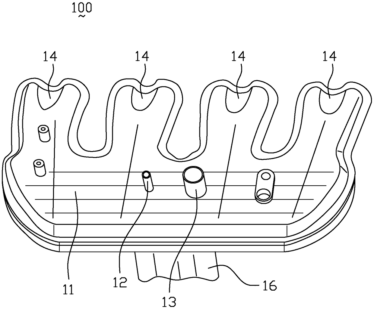
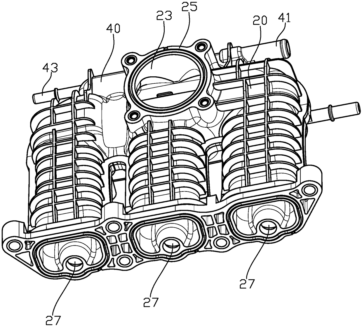
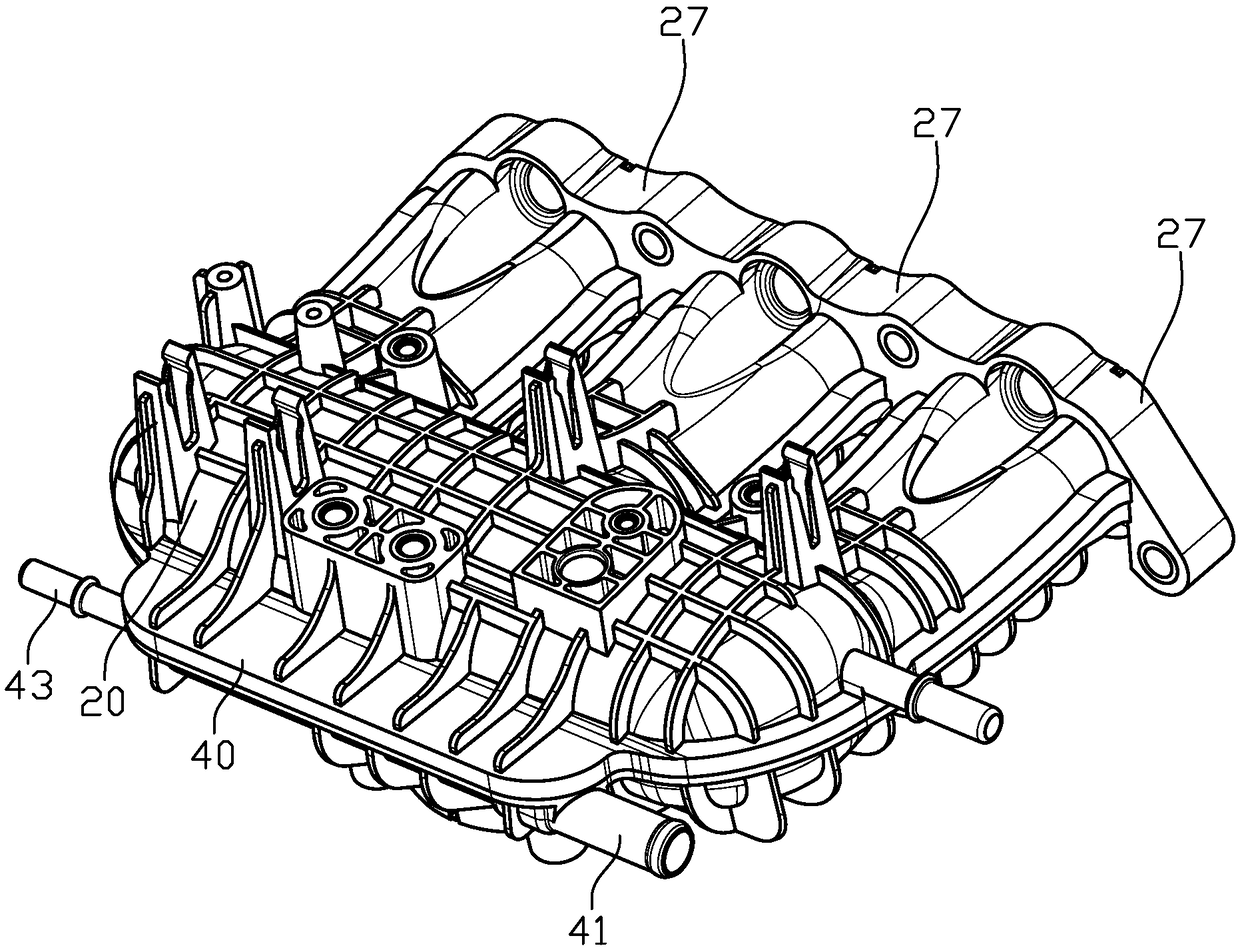
[0021] Please refer to Figure 2 to Figure 4 , the present invention provides an engine intake manifold 200 (hereinafter referred to as "intake manifold 200"), the intake manifold 200 is provided with a plenum chamber 20 and an auxiliary chamber 40 adjacent to the plenum chamber 20, The plenum chamber 20 communicates with the auxiliary chamber 40 . Specifically, a baffle 60 is provided between the plenum chamber 20 and the attached chamber 40, and at least one communication hole 61, 63, 65 is provided on the baffle 60 (there are three communication holes 61, 63, 65 shown in the figure), stabilizing The pressure chamber 20 and the auxiliary chamb...


PUM


Abstract

The invention provides an air inlet manifold of an engine and the engine comprising the air inlet manifold. A pressure stabilizing cavity and an auxiliary cavity adjacent to the pressure stabilizing cavity are formed in the air inlet manifold of the engine. The pressure stabilizing cavity communicates with the auxiliary cavity. The pressure stabilizing cavity is connected with an air outlet pipe. The air outlet pipe is connected with an air cylinder of the engine. The auxiliary cavity is connected with a crankcase ventilation pipe connector and a carbon tank electromagnetic valve pipe connector. A partition plate is arranged between the pressure stabilizing cavity and the auxiliary cavity. At least one communication hole is formed in the partition plate. The pressure stabilizing cavity communicates with the auxiliary cavity through the communication holes. By the adoption of the air inlet manifold of the engine, crankcase waste gas, fuel steam and fresh air which enter the air inlet manifold can be evenly mixed, and condensate water in a crankcase ventilation system is prevented from flowing into an electronic throttle valve.

Description

technical field [0001] The invention relates to the technical field of engines, in particular to an engine intake manifold and an engine comprising the engine intake manifold. Background technique [0002] The engine intake manifold is an important part of the engine, and its function is to ensure uniform intake and normal operation of the engine. At present, the volume of the engine, especially the supercharged gasoline engine, is getting smaller and smaller, and the volume of the intake manifold is also getting smaller and smaller; and in order to reduce fuel consumption and make the exhaust gas meet the emission requirements, the electronic devices and pipes arranged on the intake manifold There are more and more circuits and connectors, and it is more and more difficult to arrange these electronic components and connectors rationally. [0003] figure 1 It is a structural schematic diagram of an engine intake manifold 100 in the prior art. The engine intake manifold 100...

Claims


Application Information

Patent Timeline
Patent Type & Authority Patents(China)
IPC IPC(8): F02M35/104
CPCF02M35/10222F02M35/104
Inventor 徐俊锋黄英铭陈良刘巨江
Owner GUANGZHOU AUTOMOBILE GROUP CO LTD
Why Eureka
Try Eureka