Two-stage annular gap throttling device

A technology of annular gaps and throttling devices, which is applied in the direction of bearing assembly, bearings, shafts and bearings, etc., can solve the problems of difficult to arrange oil holes, cumbersome, narrowing the use range of throttles, etc., and achieve the effect of compact structure and reduced difficulty

Active Publication Date: 2019-05-14
SUZHOU CHENNA AUTOMATION TECH CO LTD
View PDF7 Cites 0 Cited by
  • Summary
  • Abstract
  • Description
  • Claims
  • Application Information

AI Technical Summary

Problems solved by technology

[0004] However, when the restrictor is used in practice, especially when it is used for opposing oil chambers, it is necessary to constantly replace the restrictor elements and adjust the pressure of the opposing oil chambers to be equal, which is relatively cumbersome
Moreover, when the structural size of the restrictor is larger than that of the supporting structure, it is difficult to arrange oil holes twice the number of oil chambers in the entire supporting structure space (one oil chamber corresponds to one throttle hole and one pressure measuring hole), which reduces the size of this section. Flow range of use

Method used


Image

  • Two-stage annular gap throttling device
  • Two-stage annular gap throttling device
  • Two-stage annular gap throttling device

Examples


Embodiment Construction

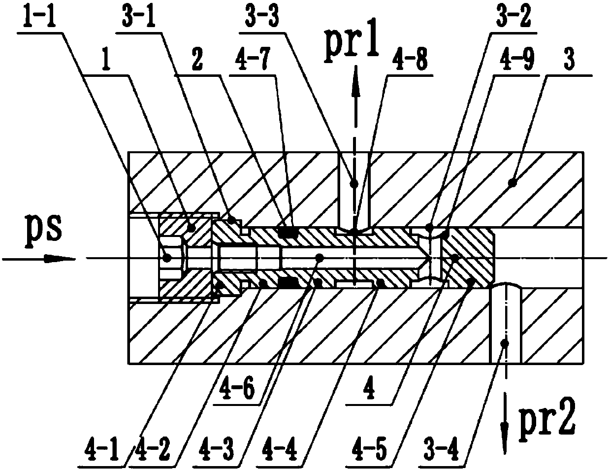
[0025] The first throttling section 4-4 and the second throttling section 4-5 of the throttle body 4 are machined with the same outer diameter and length, and the rear cavity 3-2 of the throttle mounting body 3 is Reaming process of the reamer, the first throttle section 4-4 and the second throttle section 4-5 and the rear cavity 3-2 respectively form a throttle gap, and the throttle gap is calculated according to the throttle liquid resistance of the opposite oil cavity Sure. The first installation section 4-2 and the second installation section 4-3 of the restrictor body 4 are machined with the same outer diameter and have the same outer diameter, and the installation gap between the rear cavity 3-2 and the rear cavity 3-2 is smaller than the throttling gap, about It is 1 / 7 ~ 1 / 15. After the sealing annular groove 4-7 of the restrictor body 4 is installed into the O-ring, it is axially pressed on the bottom of the front cavity 3-1 of the restrictor mounting body 3 through t...


PUM


Abstract

The invention relates to a two-section type annular gap throttling device which comprises a throttle device mounting body, a jack screw with a hole, an O-shaped sealing ring and a throttle device body. The throttle device body mounting body consists of a front cavity, a rear cavity and an oil leading hole; the throttle device body consists of a shoulder part, a mounting section, a first throttling section, a second throttling section, a sealed ring groove, a throttling ring groove, an oil inlet ring groove and a threaded oil hole; the throttle device body is used for pressing the shoulder part of the throttle device to the bottom of the front cavity of the throttle device mounting body through the jack screw with the hole, so that axial positioning is realized; the outer circle of the mounting section is matched with the rear cavity to realize radial positioning; outer diameter and length of the first throttling section are the same as those of the second throttling section; the first throttling section, the second throttling section and the rear cavity of the same size are matched to form a throttling gap which is greater than a positioning gap of the mounting section; during use, oil is introduced through the oil inlet ring groove, and flows into a group of oil storage cavities of the same structural size towards the left side and the right side separately after being throttled by the first throttling section and the second throttling section. The two-section type annular gap throttling device is compact in structure, and is easy to regulate pressure phase and the like of the oil storage cavities.

Description

technical field [0001] The invention relates to a choke used for hydrostatic support, and is especially suitable for an opposed oil cavity with a small installation space of the choke. Background technique [0002] Hydrostatic bearing has the advantages of low friction resistance, long service life, high precision and large damping, so it has a wide range of applications in ultra-precision machine tools or functional components. [0003] The restrictor is an indispensable element in the constant pressure oil supply hydrostatic support system. Commonly used traditional fixed restrictors include small orifice restrictors and capillary restrictors. Small orifice restrictors are easy to install but easy to block, while capillary restrictors are large in size and easy to block. Professor Zhao Wanhua and Professor Chen Yaolong of Xi'an Jiaotong University designed an annular gap restrictor (China CN201010102089.4), which passes through the gap between the rear end of the restrict...

Claims


Application Information

Patent Timeline
Patent Type & Authority Patents(China)
IPC IPC(8): F16C32/06F16C41/00
CPCF16C32/0648F16C41/005F16C2322/39
Inventor 陈耀龙张朋海
Owner SUZHOU CHENNA AUTOMATION TECH CO LTD
Why Eureka
Try Eureka