
A special-shaped gear transmission display device

A technology of display device and special-shaped gear, which is applied in the direction of hoisting device, portable lifting device, belt/chain/gear, etc., can solve the problem of single transmission mode, etc. The effect of good plastic workability

Active Publication Date: 2018-07-31
临沂市新天力机械有限公司
View PDF9 Cites 0 Cited by
  • Summary
  • Abstract
  • Description
  • Claims
  • Application Information

AI Technical Summary

Problems solved by technology

[0005] The purpose of the present invention is to solve the technical problem that the transmission mode in the prior art is too single, and provide a special-shaped gear transmission display device to overcome the deficiencies of the prior art

Method used


Image

  • A special-shaped gear transmission display device
  • A special-shaped gear transmission display device

Examples


Embodiment 1

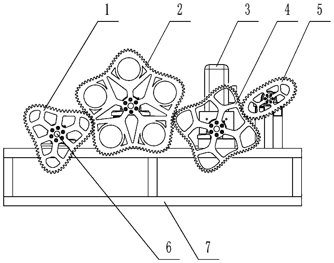
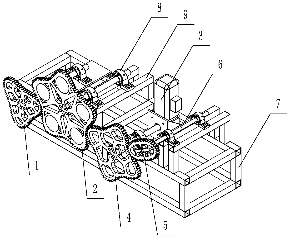
[0025] according to figure 1 with figure 2 , A special-shaped gear transmission display device, comprising a base 7; the base 7 is provided with multiple sets of brackets 9; the brackets 9 are respectively provided with a bearing seat 8 for mounting a central shaft 6, and one end of the central shaft 6 is A triangular gear 1, a five-pointed gear 2, a four-pointed gear 4, and an elliptical gear 5 meshing with each other are provided; the other end of any one of the central shafts 6 is drivingly connected with the motor.

[0026] The angles of the triangular gear 1, the pentagonal gear 2 and the quadrangular gear 4 are arcuate surfaces, and the edge line between the angles between the two arcuate surfaces is concave; the number of teeth on the arcuate surface and the concave surface is equal.

[0027] The triangular gear meshes with the pentagonal gear; the other side of the pentagonal gear meshes with the four-corner gear; the other side of the four-corner gear meshes with the oval...

Embodiment 2

[0032] A base and a support, the base and the support are an integrated structure, which is prepared according to the following process:

[0033] Step 1) Weigh each raw material in parts by weight for use: 100 parts magnesium, 20 parts aluminum, 5 parts copper, 5 parts silicon, 3 parts nickel, 2 parts molybdenum, 2 parts titanium, 1 part zirconium, 1 part zinc, 1 part vanadium Copies

[0034] Step 2) Take magnesium and heat it to 700°C under the protection of argon gas to obtain a magnesium melt;

[0035] Step 3) Take aluminum, copper, silicon, nickel, molybdenum, titanium, zirconium, zinc and vanadium, put them into a ball milling tank in turn, mix and ball mill for 12 hours to obtain powder;

[0036] Step 4) Start the resistance melting furnace, add the powder obtained in step 3) to the crucible, and pass N 2 As a protective gas, after the material to be added is completely melted, add the magnesium melt obtained in step 2), and continue to pass N 2 As a protective gas, stir for 5 m...


PUM


Abstract

The invention belongs to the technical field of mechanical transmission, and discloses a hydraulic feeding device of a special-shaped gear transmission exhibition device. The hydraulic feeding device comprises a base which is provided with multiple sets of supports; each support is provided with a bearing block where a center shaft is fixed, and one end of the center shaft is provided with a triangular gear, a pentagonal gear, a quadrangular gear and an elliptic gear which are meshed; and the other end of any center shaft is in transmission connection with a motor. The included angles of the triangular gear, the pentagonal gear and the quadrangular gear are in cambered surface, a side line between the included angles of two arc faces is in a concave surface; and the number of teeth on the arc faces is equal to the number of the teeth on the concave surface. Center shafts of the triangular gear, the pentagonal gear, the quadrangular gear and the elliptic gear are located on different horizontal planes. The hydraulic feeding device is simple in structure and novel in design, the condition of transmission through a noncircular gear and transmission under the same linear velocity and the same angle is exhibited, and the technical problem that the transmission manner in the prior art is excessively single is effectively solved.

Description

Technical field [0001] The invention belongs to the technical field of mechanical transmission and relates to a special-shaped gear transmission display device. Background technique [0002] As a high-tech exhibition platform, the Science and Technology Museum showcases various scientific and technological achievements. Gear transmission is an important transmission method in the mechanical field and is an indispensable part. [0003] At present, the gear transmissions displayed include large gears with small gears, sleeved inner and outer gears, bevel gears that change the transmission angle, etc. Although the structure is diverse, all gears are round or conical, using round and round or Cone and cone transfer energy, this transmission mode is too single, restricts the thinking of viewers, and it is difficult to improve the innovation and development ability of young students. [0004] Moreover, most of the mechanical science and technology works of the prior art use iron products,...

Claims


Application Information

Patent Timeline
Patent Type & Authority Patents(China)
IPC IPC(8): F16H55/17
CPCF16M11/04G09B25/02
Inventor 陈亮张福来杨倩韩旭宋夏娟张磊
Owner 临沂市新天力机械有限公司
Learn More