Air conditioning system and control method thereof
An air-conditioning system and refrigerant technology, applied in air-conditioning systems, heating and ventilation control systems, heating and ventilation safety systems, etc., can solve problems such as insufficient dehumidification and insufficient heating, so as to avoid insufficient dehumidification and reduce energy consumption , to avoid the effect of uneven temperature distribution
- Summary
- Abstract
- Description
- Claims
- Application Information
AI Technical Summary
Problems solved by technology
Method used
Image
Examples
Embodiment approach 1
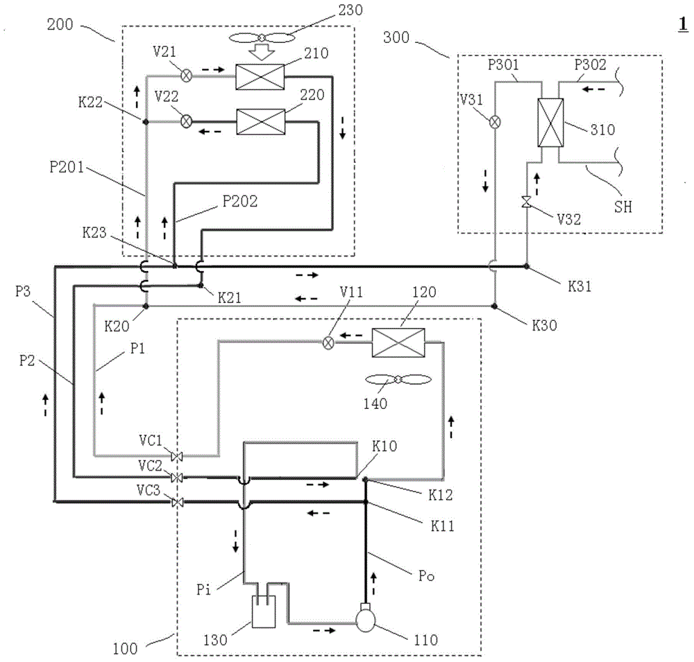
[0137] First, refer to figure 1 , the circuit configuration of the air conditioning system 1 according to Embodiment 1 of the present invention will be described in detail.
[0138] Such as figure 1 As shown, the air conditioning system 1 of this embodiment includes an outdoor unit 100, a dehumidifying and heating indoor unit 200, and a refrigerant-water heat exchange unit 300. A plurality of connection pipes including the one connection pipe P1, the second connection pipe P2, and the third connection pipe P3 are connected to each other.
[0139] Here, stop valves VC1 to VC3 are provided in the middle of the first connection pipe P1, the second connection pipe P2, and the third connection pipe P3 (hereinafter, the range of the outdoor unit is also delimited by the stop valves VC1 to VC3). ). Under normal circumstances, the stop valves VC1-VC3 are all in a normally open state. In addition, in some cases, any one or more, or even all, of the cut-off valves VC1-VC3 may also...
Embodiment approach 2
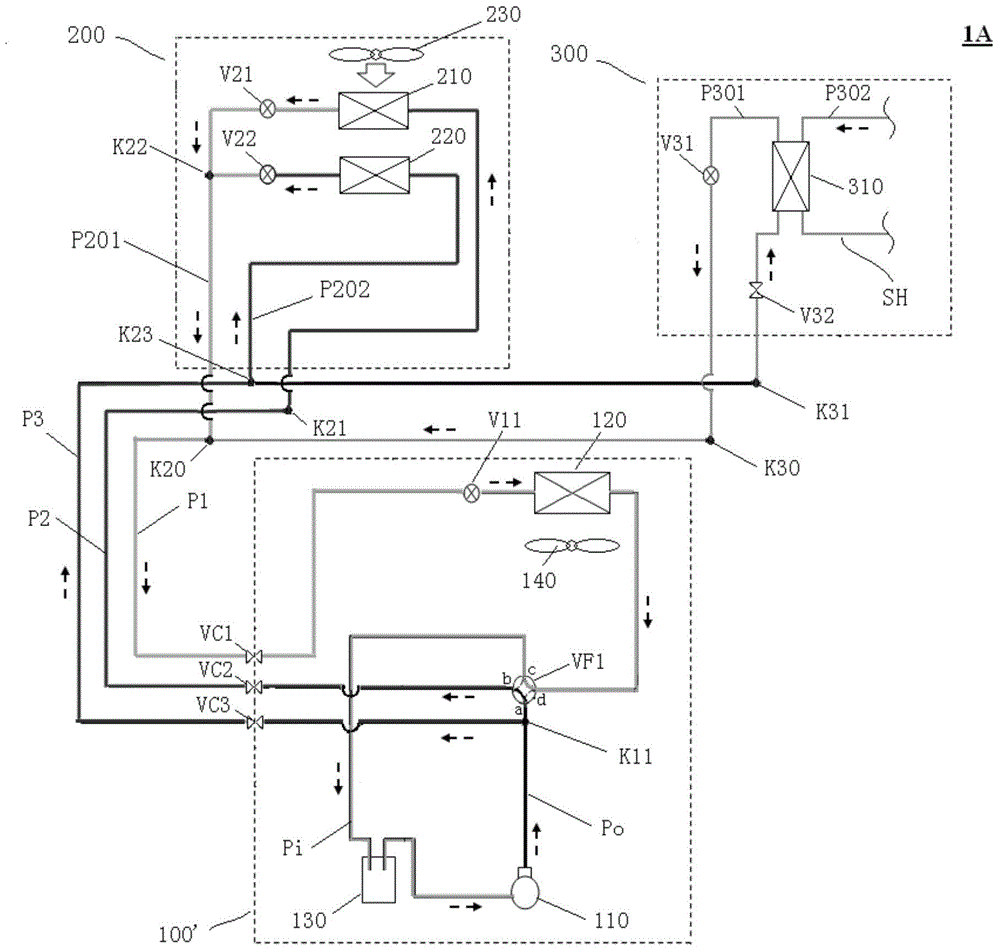
[0174] First, refer to figure 2 , to describe the circuit structure of the air conditioning system 1A according to Embodiment 2 of the present invention, wherein, in figure 2 In , the same reference numerals are given to the same components as those in Embodiment 1 described above.
[0175] In addition, since the air-conditioning system 1A of Embodiment 2 is basically the same as the air-conditioning system 1 of the above-mentioned Embodiment 1 in terms of configuration, differences from the above-mentioned Embodiment 1 will be mainly described below.
[0176]In this embodiment, the outdoor unit 100' includes a four-way switching valve VF1 (equivalent to the first switching device in the present invention), and the four-way switching valve VF1 can switch between the first switching state and the second switching state, Among them, in the first switching state of the four-way switching valve VF1, the first connecting pipe P1 communicates with the discharge pipe Po and the se...
Embodiment approach 3
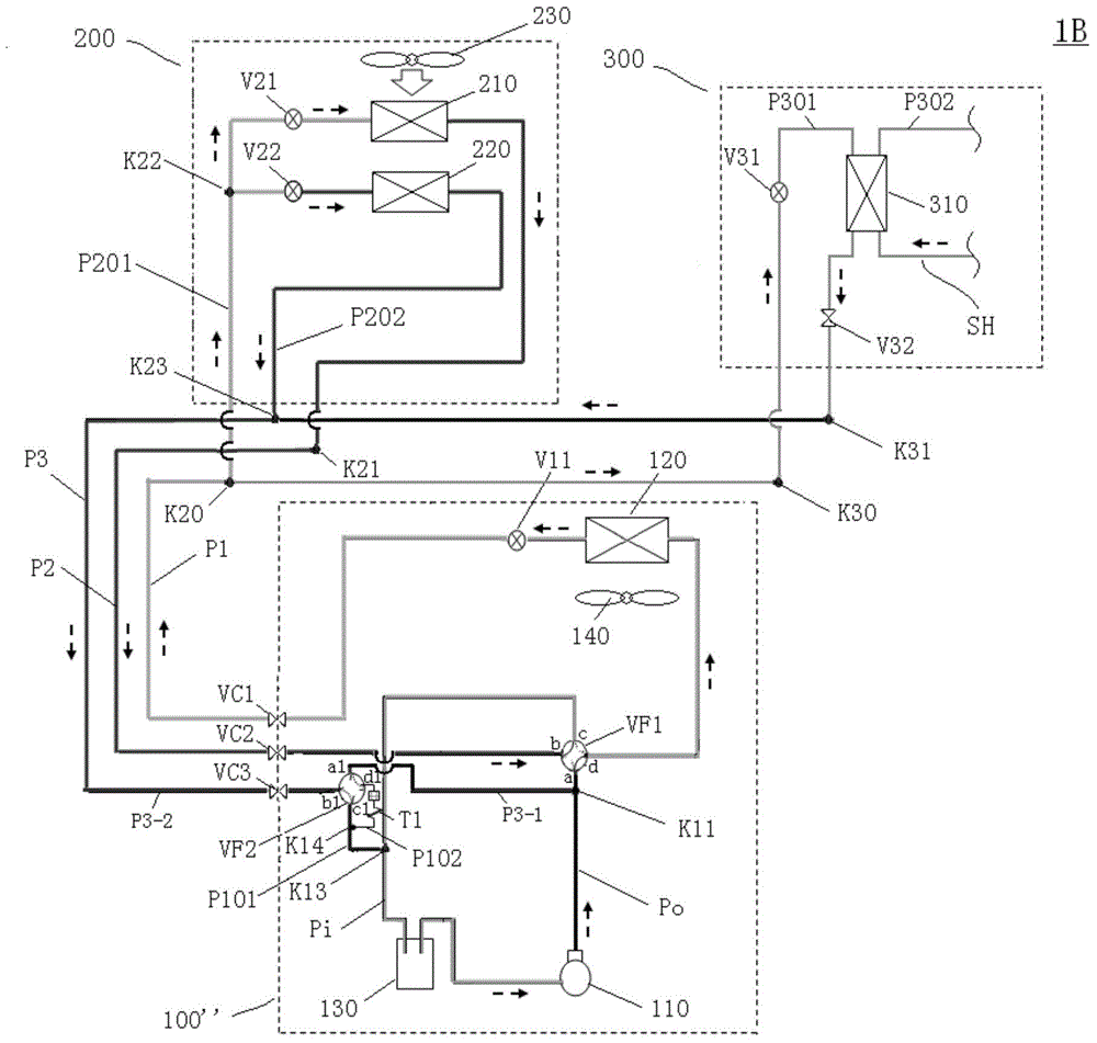
[0199] First, refer to image 3 , to describe the circuit structure of the air conditioning system 1B according to Embodiment 3 of the present invention, wherein, in image 3 In , the same reference signs are attached to the same components as those in Embodiment 2 above.
[0200] In addition, since the air-conditioning system 1B of Embodiment 3 is basically the same as the air-conditioning system 1A of the above-mentioned Embodiment 2 in terms of configuration, differences from the above-mentioned Embodiment 2 will be mainly described below.
[0201] In this embodiment, an end (located at the image 3 The end at the midpoint K13) the first outdoor branch pipe P101 connected to the suction pipe Pi.
[0202] And, the third connecting pipe P3 has a first part P3-1 (from image 3 The part from point K11 in the following four-way switching valve VF2 to the port a1 of the following four-way switching valve) and the second part P3-2 (from the port b1 of the following four-way swi...
PUM
 Abstract
Description
Claims
Application Information
 - R&D
- Intellectual Property
- Life Sciences
- Materials
- Tech Scout
- Unparalleled Data Quality
- Higher Quality Content
- 60% Fewer Hallucinations
Browse by: Latest US Patents, China's latest patents, Technical Efficacy Thesaurus, Application Domain, Technology Topic, Popular Technical Reports.
© 2025 PatSnap. All rights reserved.Legal|Privacy policy|Modern Slavery Act Transparency Statement|Sitemap|About US| Contact US: help@patsnap.com


