Refrigerating system and heat exchanger thereof

A refrigeration system and condenser technology, applied in the field of refrigeration systems and their heat exchangers, can solve the problems of increased production process difficulty, increased economic and time costs, etc., and achieve the goals of easy implementation, increased economic and time costs, and improved performance Effect

Active Publication Date: 2016-11-23
HANGZHOU SANHUA RES INST CO LTD
View PDF8 Cites 7 Cited by
  • Summary
  • Abstract
  • Description
  • Claims
  • Application Information

AI Technical Summary

Problems solved by technology

[0006] The problem to be solved by the present invention is to avoid problems such as increased production process difficulty, increased economic and time c

Method used


Image

  • Refrigerating system and heat exchanger thereof
  • Refrigerating system and heat exchanger thereof
  • Refrigerating system and heat exchanger thereof

Examples


Example Embodiment

[0033] The present invention will be described in detail below with specific embodiments in conjunction with the accompanying drawings.

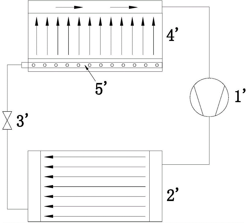
[0034] One of the embodiments of the refrigerating system (such as "air conditioning system") of the present invention starts from the outlet header of the micro-channel condenser, that is, distributes the refrigerant entering the micro-channel evaporator from the single-phase liquid refrigerant, thereby realizing Better distribution of refrigerant in the evaporator improves system performance and reduces costs.

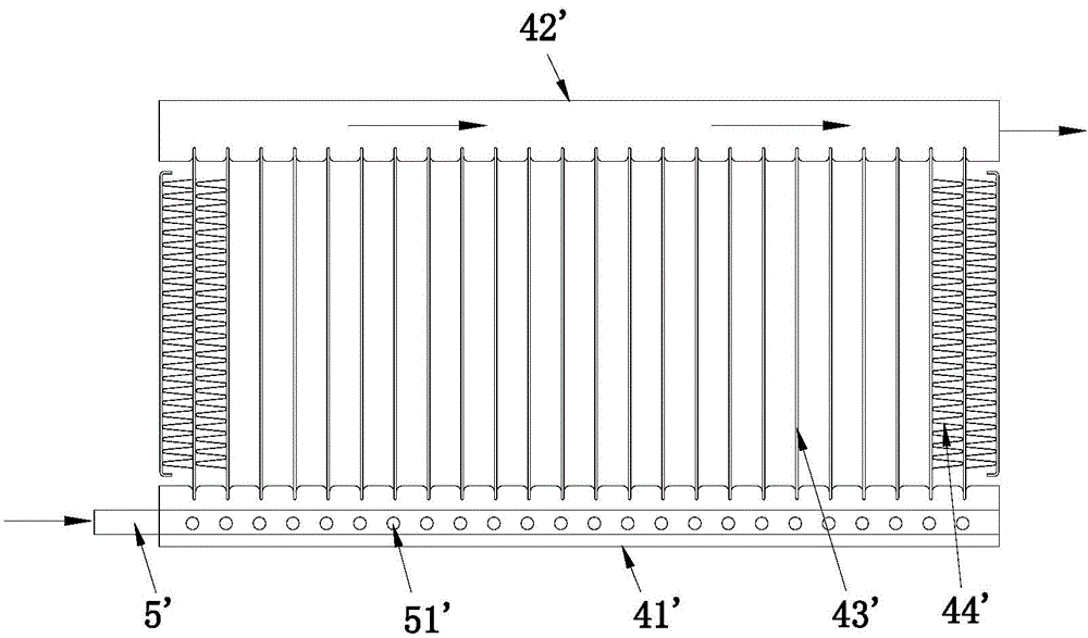
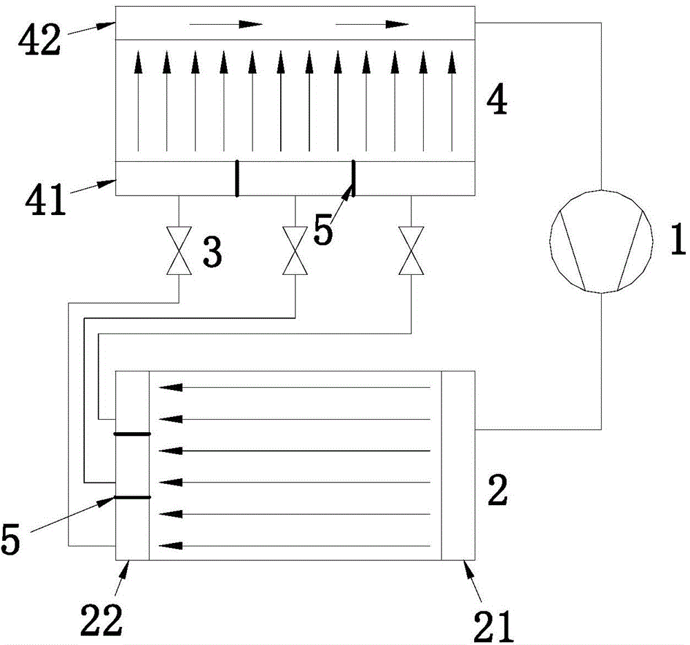
[0035] image 3 It is a schematic diagram of the principle of this embodiment. like Figure 3-Figure 6 As shown, the system includes a compressor 1 , a microchannel condenser 2 , a throttling device 3 and a microchannel evaporator 4 . On the outlet header 22 of the microchannel condenser 2 and the inlet header 41 of the microchannel evaporator 4, one or more n (n≥1) partitions 5 are correspondingly arranged, and the partitions 5...


PUM


Abstract

The invention relates to a refrigerating system, which comprises a compressor, a micro-channel condenser, a micro-channel evaporator and at least one throttling device. Both the micro-channel condenser and the micro-channel evaporator comprise inlet end collecting pipes and outlet end collecting pipes; a plurality of flat pipes communicate between each inlet end collecting pie and the corresponding outlet end collecting pipe; the throttling devices are arranged between the micro-channel condenser and the micro-channel evaporator; the inlet end collecting pipe of the micro-channel evaporator is divided into multiple (n+1) sequentially arranged collecting pipe sections through a plurality of (n, n is larger than or equal to 1) clapboards; each two adjacent collecting pipe sections are relatively separated through each clapboard; each collecting pipe section communicates with a certain number of flat pipes, and is provided with at least one interface connected with pipelines, so that distributing pipes used for distributing do not need to be arranged in the collecting pipes, and the system is simple in structure and easy to implement.

Description

technical field [0001] The invention belongs to the technical field of refrigeration, and in particular relates to a refrigeration system and a heat exchanger thereof. Background technique [0002] At present, in the field of refrigeration technology, copper tube-fin (tube-fin) heat exchangers occupy a dominant position due to their simple processing technology and low cost. The tube-fin type is generally composed of round tubes and various types of fins. The round tubes and fins are connected by expansion tubes. The contact thermal resistance is large, the heat transfer coefficient is low, and relative movement between the tubes and fins is easy to occur. The holes on the chip are gradually enlarged, which will reduce the heat transfer efficiency and shorten the service life. As a new type of high-efficiency and compact heat exchanger, the microchannel heat exchanger has become a current research hotspot, and has been applied in automobile air conditioners and large commer...

Claims


Application Information

Patent Timeline
IPC IPC(8): F25B39/00F28F9/22F28F9/02
Inventor 不公告发明人
Owner HANGZHOU SANHUA RES INST CO LTD
Why Eureka
Try Eureka