
Power System with Reduced Output Ripple

A power supply system and output ripple technology, applied in the field of electronics, can solve problems such as large system noise and affect system performance, and achieve the effect of improving performance, reducing output ripple voltage, and realizing synchronous charging or synchronous discharging.

Active Publication Date: 2018-12-21
SPREADTRUM COMM (SHANGHAI) CO LTD
View PDF3 Cites 0 Cited by
  • Summary
  • Abstract
  • Description
  • Claims
  • Application Information

AI Technical Summary

Problems solved by technology

The charge pump is a switching power supply that uses capacitors as energy storage elements. It controls the charging and discharging of capacitors by controlling the array of switching tubes to realize voltage conversion. Its characteristics are based on those between linear regulators and inductive switching power supplies. High efficiency and relatively simple peripheral circuits are widely used in systems requiring negative power supply, combined with figure 1 The circuit diagram of the power system and Figure 2 to Figure 4 It can be seen from the charging and discharging timing diagram of the BUCK converter that due to factors such as the on and off of the MOSFET, the energy storage and release of the inductive element, and the charging and discharging of the capacitive element, a large ripple voltage is often generated. In the charge pump circuit, the charge transfer factor will also cause ripple, and the interference of the ripple voltage will cause a large noise in the system and affect the performance of the system.

Method used


Image

  • Power System with Reduced Output Ripple
  • Power System with Reduced Output Ripple
  • Power System with Reduced Output Ripple

Examples


Embodiment Construction

[0047] The following will clearly and completely describe the technical solutions in the embodiments of the present invention with reference to the accompanying drawings in the embodiments of the present invention. Obviously, the described embodiments are only some, not all, embodiments of the present invention. Based on the embodiments of the present invention, all other embodiments obtained by persons of ordinary skill in the art without creative efforts fall within the protection scope of the present invention.

[0048] It should be noted that, in the case of no conflict, the embodiments of the present invention and the features in the embodiments can be combined with each other.

[0049] The present invention will be further described below in conjunction with the accompanying drawings and specific embodiments, but not as a limitation of the present invention.

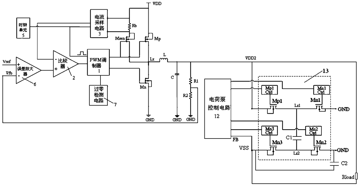
[0050] refer to Figure 5 As shown, the output ripple power system is reduced, which includes,

[0051] BUCK c...


PUM


Abstract

The present invention relates to the field of the electron technology, concretely to a power supply system for reducing output ripples. The system comprises: a BUCK converter including a work circuit provided with energy storage elements which can switch between a charging mode and a discharging module in the action of pulse width modulation signals to output first voltage; a control circuit configured to generate pulse width modulation signals in the action of clock pulse signals, voltage feedback signals and current detection signals generated by a clock unit; a charge pump circuit including a voltage regulation circuit configured to convert the first voltage to negative voltage; and a charge pump control circuit configured to connect with the clock unit and configured to generate switch control signals in the action of the clock unit in the condition that the work circuit and the voltage regulation circuit are both located in the charging mode or the work circuit and the voltage regulation circuit are both located in the discharging circuit. The BUCK converter and the charge pump circuit commonly use the same clock source to realize synchronous charge or synchronous discharge so as to reduce the output ripple voltage and improve the performance appearance of the system.

Description

technical field [0001] The invention relates to the field of electronic technology, in particular to a power supply system. Background technique [0002] For portable electronic products powered by batteries, the power supply system is often required to provide positive and negative voltages. The power supply system in the prior art reduces an input high voltage to a lower voltage through a BUCK converter to output a voltage, and the output voltage is passed through at the same time. The charge pump circuit converts to obtain a stable negative voltage output. The charge pump is a switching power supply that uses capacitors as energy storage elements. It controls the charging and discharging of capacitors by controlling the array of switching tubes to achieve voltage conversion. Its characteristics are based on those between linear regulators and inductive switching power supplies. High efficiency and relatively simple peripheral circuits are widely used in systems that requ...

Claims


Application Information

Patent Timeline
Patent Type & Authority Patents(China)
IPC IPC(8): H02M3/155H02M3/07H02M1/14
Inventor 樊茂朱小荣
Owner SPREADTRUM COMM (SHANGHAI) CO LTD
Learn More