

Ignition device for internal combustion engine
An ignition device and internal combustion engine technology, applied in the direction of ignition safety devices, engine ignition, and other devices, can solve problems such as increased burden, and achieve the effects of improving reliability, avoiding damage, and avoiding bad conditions
- Summary
- Abstract
- Description
- Claims
- Application Information
AI Technical Summary
Problems solved by technology
Method used
Image

Examples
Embodiment 1
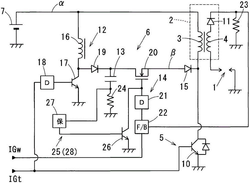
[0041] refer to figure 1 , figure 2 Example 1 will be described.
[0042] The ignition device of the first embodiment is used in a spark ignition engine for running a vehicle, and ignites the air-fuel mixture in the combustion chamber at a predetermined ignition timing. In addition, an example of the engine is a direct-injection engine capable of performing lean burn (lean burn) using gasoline as fuel. This engine is equipped with an EGR (exhaust gas recirculation) device that returns a part of the exhaust gas to the engine intake side as EGR gas, and also has a swirling device that generates a swirling flow (tumble or swirl, etc.) of the air-fuel mixture in the cylinder. flow control mechanism.
[0043] The ignition device of the first embodiment is a DI (abbreviation for direct ignition) type in which a corresponding ignition coil 2 is used for each spark plug 1 of each cylinder.
[0044] This ignition device controls the energization of the primary coil 3 of the ignit...
Embodiment 2
[0111] refer to figure 1 , figure 2 Example 2 will be described. The basic structure of embodiment 2 is the same as that of embodiment 1, so the figure of embodiment 2 follows the figure of embodiment 1. In addition, in each of the following Examples, the same code|symbol as Example 1 mentioned above represents the same functional thing.
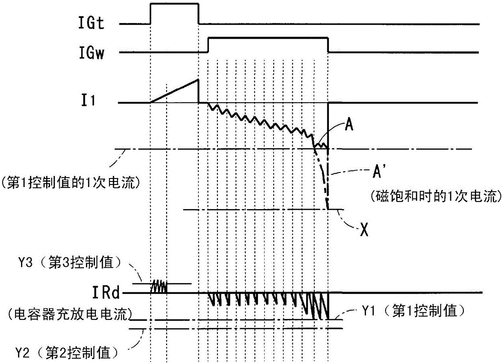
[0112] In the first embodiment described above, an example was shown in which the switching mechanism 20 for energy input is controlled so that the primary coil 3 is not magnetically saturated.
[0113] On the other hand, in this second embodiment, when the primary current approaches the saturation current value X, the input of electric energy to the primary coil 3 is stopped to avoid magnetic saturation of the primary coil 3 .
[0114] The mechanism for avoiding the magnetic saturation of the primary coil 3 according to the second embodiment includes:
[0115] · The same primary side current detection mechanism 24 as in Embodiment 1; ...
Embodiment 3
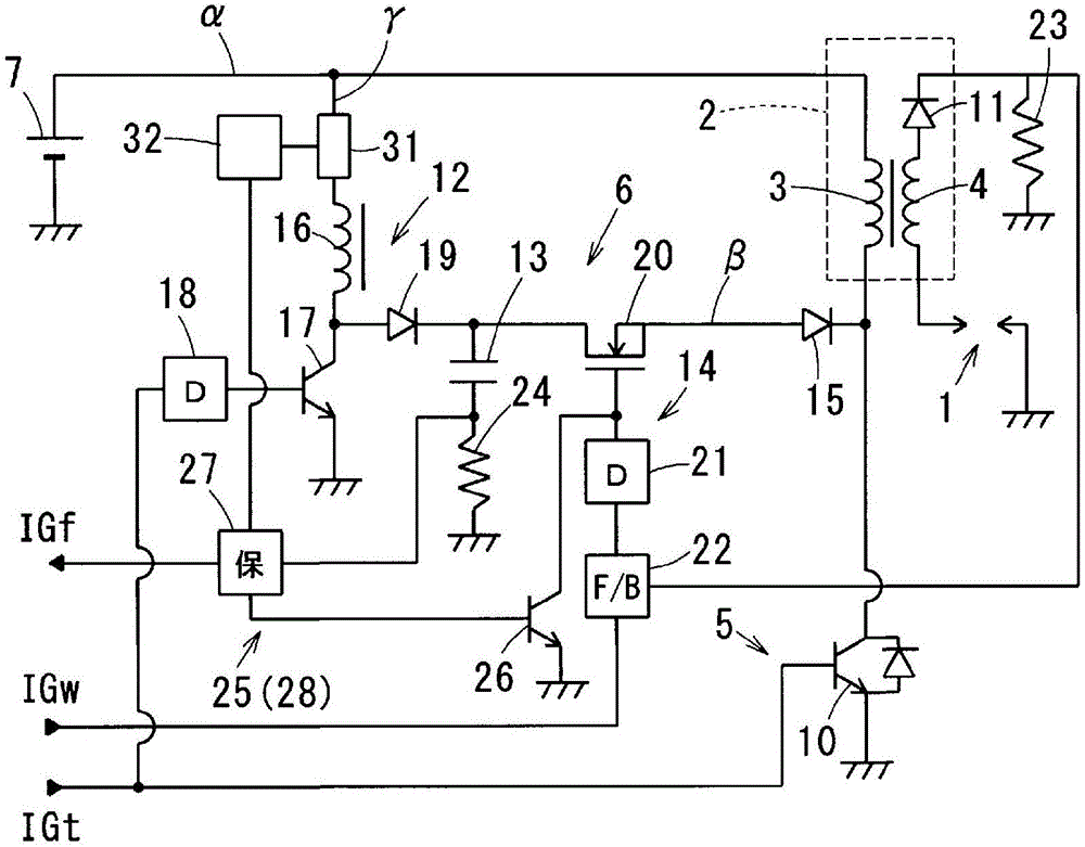
[0129] refer to figure 2 , image 3 Example 3 will be described.
[0130] The protection circuit 27 of the third embodiment performs failure determination of the energy input circuit 6 based on the capacitor discharge current or the capacitor charge current detected by the primary side current detection mechanism 24, stops the energy input circuit 6 at the time of failure determination, and sends a signal to the ECU. Output failure judgment signal IGf to notify ECU of failure occurrence.
[0131] The main points of embodiment 3 are:
[0132] (a) Turn OFF the power supply unit to the booster circuit 12 at the time of failure determination;
[0133] (b) Based on the capacitor discharge current detected by the primary side current detection mechanism 24, the failure determination of the energy input circuit 6 is performed;
[0134] (c) Based on the capacitor charging current detected by the primary-side current detection means 24, failure determination of the energy input ci...
PUM
 Abstract
Description
Claims
Application Information