Cleaning machine

A cleaning machine and cleaning mechanism technology, applied in the direction of dryers, cleaning hollow objects, cleaning methods and utensils, etc., can solve the problems of elongating the size of the whole machine, increasing the floor area of ​​the whole machine, and poor drying effect, etc. Achieve the effect of reducing the floor area, simple and compact structure, and improving the drying effect

Active Publication Date: 2016-11-30
TRUKING TECH LTD
View PDF12 Cites 4 Cited by
  • Summary
  • Abstract
  • Description
  • Claims
  • Application Information

AI Technical Summary

Problems solved by technology

In this structure, limited by the design of the length of the auger, the time for the ampoules to pass through the blowing section is short, and the drying effect is poor, especially the production capacity cannot

Method used


Image

  • Cleaning machine
  • Cleaning machine
  • Cleaning machine

Examples


Embodiment Construction

[0030] The present invention will be further described in detail below in conjunction with the accompanying drawings and specific embodiments.

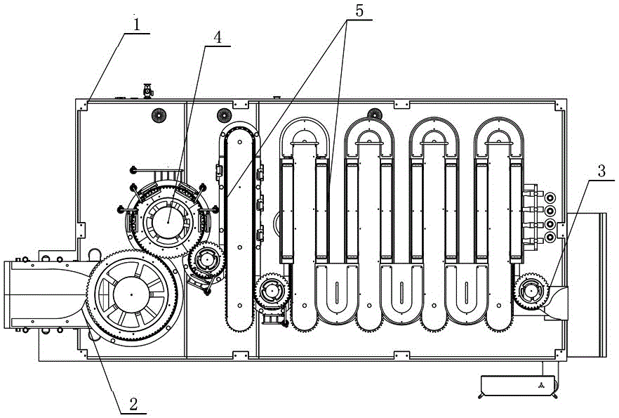
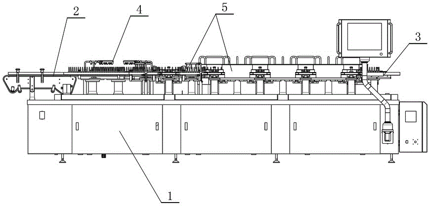
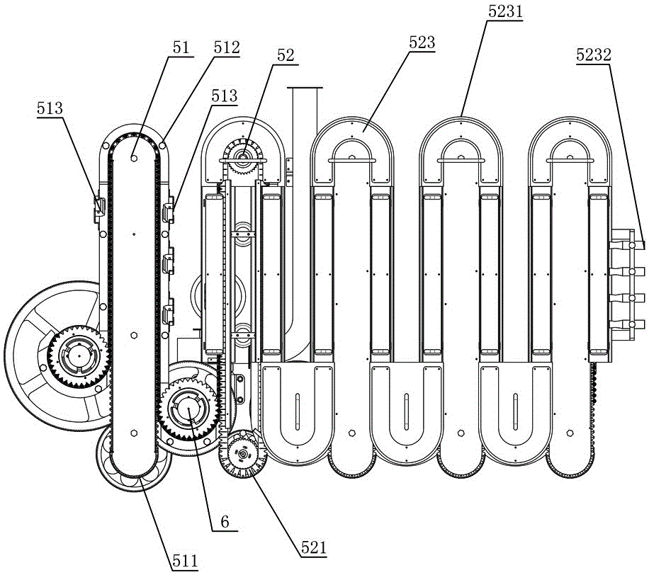
[0031] Figure 1 to Figure 10 A kind of embodiment of cleaning machine of the present invention is shown, and this cleaning machine comprises frame 1, and frame 1 is respectively equipped with bottle-feeding mechanism 2 and bottle-out mechanism 3 in the head and tail section, and frame 1 is on bottle-feeding mechanism 2 A cleaning mechanism 4 docked with the bottle inlet mechanism 2 is installed between the bottle outlet mechanism 3, and a bottle blowing conveying mechanism 5 with an S-shaped bottle delivery path is docked between the cleaning mechanism 4 and the bottle outlet mechanism 3 on the frame 1 . In this structure, the bottle body enters the cleaning mechanism 4 through the bottle feeding mechanism 2 for cleaning, and then enters the bottle blowing conveying mechanism 5 in an S-shaped bottle conveying path for blowing and dr...


PUM


Abstract

The invention discloses a cleaning machine comprising a rack. A bottle feeding mechanism and a bottle discharging mechanism are installed to head and tail sections of the rack respectively, a cleaning mechanism in butt joint with the bottle feeding mechanism is arranged between the bottle feeding mechanism and the bottle discharging mechanism on the rack, and a blown bottle conveying mechanism with an S-shaped bottle conveying path is in butt joint with the position between the cleaning mechanism and the bottle discharging mechanism on the rack. The cleaning machine has the advantages of simple and compact structure, and capabilities of improving blow-drying effect and capacity and reducing whole machine occupied area.

Description

technical field [0001] The invention mainly relates to food and pharmaceutical packaging machinery, in particular to a washing machine. Background technique [0002] The cleaning machine generally includes a cleaning section, a cold air blowing section and a hot air blowing section. The bottle body is conveyed by a wide mesh belt into the first section of the long auger. Blow bottle with compressed air. Then the bottle body enters the second section of long auger for conveying, blows the bottle through hot air, and finally directly exits the bottle to connect to the subsequent equipment. In this structure, limited by the design of the length of the auger, the time for the ampoule to pass through the blowing section is short, and the drying effect is poor, especially the production capacity cannot be too large, only about 100 bottles; too long auger requires high material and processing requirements , easy to wear, and will elongate the size of the whole machine, increasing...

Claims


Application Information

Patent Timeline
IPC IPC(8): B08B9/20B08B9/42B08B9/44F26B21/00
CPCB08B9/205B08B9/42B08B9/426B08B9/44F26B21/00
Inventor 郭志刚李新华蔡大宇
Owner TRUKING TECH LTD
Why Eureka
Try Eureka