Energy-saving environment-friendly efficient water drainage and silt removal device for flue gas desulfurization chimney

An energy-saving and environmentally friendly chimney technology, which is applied in the treatment of gaseous effluent wastewater, flocculation/sedimentation water/sewage treatment, and combustion product treatment, can solve the problems of chimney air tightness, deterioration of the operating environment, and high risk To achieve the effect of keeping the chimney unobstructed, easy to promote, and long service life

Active Publication Date: 2016-11-30
蒙自矿冶有限责任公司
View PDF5 Cites 4 Cited by
  • Summary
  • Abstract
  • Description
  • Claims
  • Application Information

AI Technical Summary

Problems solved by technology

[0002] After the desulfurization and dust removal of the flue gas reaches the standard, it is discharged through the chimney at high altitude. There are still trace dust and water vapor in the flue gas, which settles on the inner wall of the chimney due to gravity during the process of rising in the chimney, and flows to the bottom of the chimney. Generally, a discharge pipe is installed directly below the bottom of the chimney. Otherwise, the chimney will be blocked by the underflow of condensation and sedimentation. Equipment maintenance and sludge discharge must be carried out at high altitudes, which is very dangerous. At the same time, the airtightness of the chimney will be affected when the sludge is discharged, and low-concentration exhaust gas will leak from the discharge port. , deteriorating the operating environment

Method used


Image

  • Energy-saving environment-friendly efficient water drainage and silt removal device for flue gas desulfurization chimney

Examples


Embodiment Construction

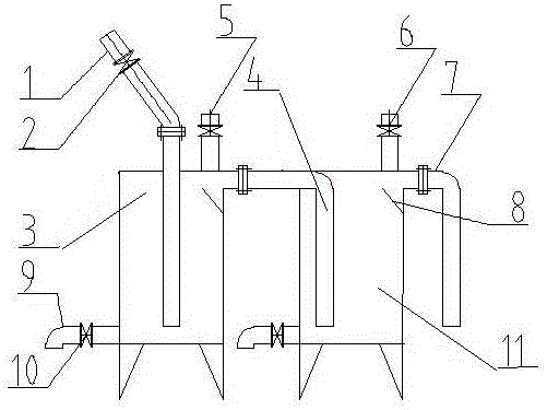
[0025] Further illustrate the present invention below in conjunction with accompanying drawing. These descriptions are for better expressing and understanding the beneficial effects of the present invention, rather than limiting the present invention.

[0026] Such as figure 1 As shown, this high-efficiency flue gas desulfurization chimney drainage and silt discharge device of the present invention includes a diversion pipe 1 for sewage discharge at the bottom of the high-altitude chimney. , and vertically stretch into the tank body simultaneously, the top of the drain tank has an upper conduit 4 connected with the top of the drain tank two and vertically stretches into the inside of the drain tank two, and the top of the two drain tanks has a water-adding pipe 5 and a ball valve 6. The outlet of the upper drainage pipe 7 of the drainage tank two is located at the overflow port, and the outlet reaches the ground collection ditch. The drainage baffles 8 of the two drain tanks...


PUM


Abstract

The invention discloses an energy-saving environment-friendly efficient water drainage and silt removal device for a flue gas desulfurization chimney. The device comprises a first drainage tank and a second drainage tank and is characterized in that both the first drainage tank and the second drainage tank are airtight container, the first drainage tank is communicated with the second drainage tank through an upper conduit, an inlet of the upper conduit is located at an upper overflow port of the first drainage tank, and an outlet of the upper conduit is located in the bottom of the second drainage tank and spaced from the bottom surface; the first drainage tank is communicated with the bottom of the high-altitude chimney through a diversion pipe, a water adding pipe provided with a brake valve is arranged on the top of the first drainage tank, a water adding pipe provided with a brake valve is arranged on the top of the second drainage tank, a lower drainage pipe provided with a brake valve is arranged on the bottom of the first drainage tank, and a lower drainage pipe provided with a brake valve is arranged on the bottom of the second drainage tank; the upper portion of the second drainage tank is communicated with the outside through an upper drainage pipe, an inlet of the upper drainage pipe is located at an overflow port of the second drainage tank, and the diversion pipes and the water feeding pipes are provided with control valves respectively. By the adoption of the device, water accumulated in the flue gas desulfurization chimney can be efficiently and automatically dredged, dust can be discharged, the chimney can be kept clear, dangers of manual aerial cleaning work are avoided, operation is easy and convenient, and the device is safe, environment friendly, low in manufacturing cost and easy to popularize.

Description

technical field [0001] The invention relates to an energy-saving and environment-friendly flue gas desulfurization chimney high-efficiency drainage and silt discharge device. Background technique [0002] After the desulfurization and dust removal of the flue gas reaches the standard, it is discharged through the chimney at high altitude. There are still trace dust and water vapor in the flue gas, which settles on the inner wall of the chimney due to gravity during the process of rising in the chimney, and flows to the bottom of the chimney. Generally, a discharge pipe is installed directly below the bottom of the chimney. Otherwise, the chimney will be blocked by the underflow of condensation and sedimentation. Equipment maintenance and sludge discharge must be carried out at high altitudes, which is very dangerous. At the same time, the airtightness of the chimney will be affected when the sludge is discharged, and low-concentration exhaust gas will leak from the discharge ...

Claims


Application Information

Patent Timeline
Patent Type & Authority Applications(China)
IPC IPC(8): F23J3/02C02F1/52C02F103/18
CPCC02F1/52C02F2103/18F23J3/026
Inventor 覃健杰陈佐红张柏翟荣华
Owner 蒙自矿冶有限责任公司
Why Eureka
Try Eureka