A mold for pressing metal rubber material

A technology of metal rubber and mould, which is applied in the direction of manufacturing tools, metal processing equipment, forming tools, etc., can solve problems such as jamming and no mention of jamming, so as to reduce the trouble of replacing molds, improve the phenomenon of jamming, and reduce costs. Effect

Active Publication Date: 2017-11-28
HARBIN ENG UNIV
View PDF3 Cites 1 Cited by
  • Summary
  • Abstract
  • Description
  • Claims
  • Application Information

AI Technical Summary

Problems solved by technology

[0004] Application number: 01116733.5, the Chinese patent titled the preparation method of metal rubber materials does not mention the solution to the jamming during the pressing process, and the above-mentioned patents mainly focus on thermal stabilization treatment. The present invention emphasizes on improving the jamming problem during the compression process , the main pressing object is through-hole metal rubber

Method used


Image

  • A mold for pressing metal rubber material
  • A mold for pressing metal rubber material
  • A mold for pressing metal rubber material

Examples


Embodiment 1

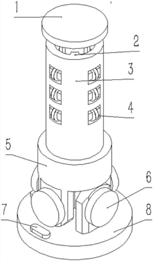
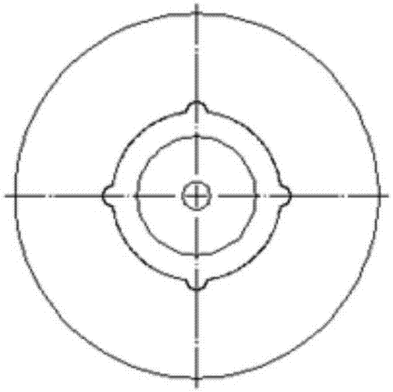
[0020] Example 1: Combining Figure 1 to Figure 6 , a new mold for pressing metal rubber materials of the present invention includes an upper pressing rod 1, a retractable metal sheet 2, a pressing rod guide shell 3, a U-shaped ball bearing 4, a punch base 5, a cross shaft 6, a bubble level 7, Guide base 8, metal rod 9. Wherein the upper pressing rod is inserted into the inside of the pressing rod guide shell, and the four protruding circular arcs cooperate with the U-shaped ball bearings. The boss on the punch base is inserted into the circular groove of the upper pressing rod, and at this time the pressing rod guide shell is inserted into the annular groove of the punch base.

[0021] That is the present invention comprises compression device and base two major parts. The compression device includes a pressing bar guide shell 3, a U-shaped ball bearing 4, a punch base 5 and an upper pressing bar 1. The base part includes a guide base 8 and a bubble level 7 . The ball bea...

Embodiment 2

[0024] Embodiment 2: Based on the above-mentioned embodiment, the present invention can also be: the bubble level is arranged on the guide base in the horizontal and vertical directions, that is, the bubble level is arranged on the base, and respectively arranged along the front, rear and left and right directions One. The bubble level on the guide base can keep the mold at a preliminary level when it is put into the compressor.

Embodiment 3

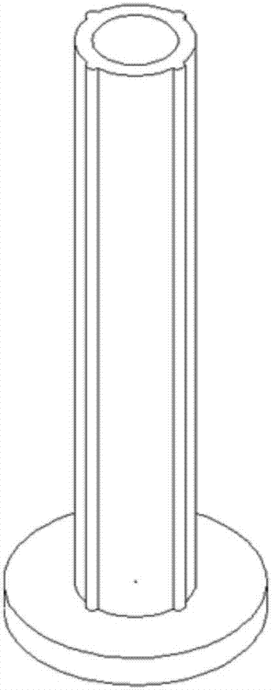
[0025] Embodiment 3: Based on the above embodiment, the present invention can also be: a length scale that can read the amount of compression is arranged on the long rod of the upper pressing tool, that is, the upper pressing rod is provided with a length scale, which can easily read the compression quantity.


PUM


Abstract

The invention discloses a novel metal rubber material pressing mould. The novel metal rubber material pressing mould comprises a compression device and a base part. The compression device comprise a compression bar guide shell, U-shaped ball bearings, a male die base and an upper compression bar; and the base part comprises a guide base and a vacuole leveling instrument. The ball bearings are installed on the compression bar guide shell in the annular direction; and four groups of the ball bearings are installed in the annular direction, and each group has three ball bearings. An upper pressing mould body is placed in the compression bar guide shell, and protruded tracks on the compression bar are matched with the U-shaped ball bearings. A protruded part of the male die base is inserted into the upper compression bar, and the compression bar guide shell is inserted into a groove of the male die. The male die and the guide base of the base part are connected through a cross-shaped shaft. According to the novel metal rubber material pressing mould, stuck phenomenon in a pressing process can be remarkably improved, so that the cost is reduced, and the trouble of replacing the mould is saved; main pressing objects of the novel metal rubber material pressing mould are metal rubbers with through holes; manufacturing cost of the mould is low; and the volume is smaller and the mould is more portable.

Description

technical field [0001] The invention relates to a mold, in particular to a mold for pressing metal rubber materials, and belongs to the technical field of metal rubber pressing mold structures. Background technique [0002] Metal rubber is a network structure made of interlaced metal wires, and its performance is similar to that of rubber polymer materials. The preparation process is to stretch a certain quality metal mesh, then extrude the required size of the lines, and put them into the mold in an orderly manner according to the shape of the processed test piece for compression molding. The more common molds currently used include an upper pressing plate, a lower punch, a metal rod, two pressing rods and a sleeve. Its disadvantages are obvious: it is easy to get the metal rubber of the desired shape or get stuck due to the uneven placement of the metal mesh in the mold or the insufficient level of the pressure tool in the universal testing machine, which in turn leads to...

Claims


Application Information

Patent Timeline
Patent Type & Authority Patents(China)
IPC IPC(8): B21D37/10
CPCB21D37/10
Inventor 唱忠良范永琦邹广平刘松
Owner HARBIN ENG UNIV
Why Eureka
Try Eureka