Electronic beam repair welding method for friction stir welding tunnel defects

A technology of friction stir welding and electron beam, which is applied in welding equipment, arc welding equipment, application, etc., can solve the problems of cost and cycle increase, and the flatness of parts cannot be guaranteed, so as to prevent root defects, avoid nail tip effect, avoid The effect of lack of weld material

Active Publication Date: 2016-12-07
CHINA ELECTRONIC TECH GRP CORP NO 38 RES INST
View PDF7 Cites 7 Cited by
  • Summary
  • Abstract
  • Description
  • Claims
  • Application Information

AI Technical Summary

Problems solved by technology

The tunnel defect of the part finishing is exposed. At this time, because there is no machining allowance, the repair welding method of friction stir welding cannot be used, and the repair welding of argon arc welding will cause a large deformation of the part, and the flatness of the part after repair welding cannot be guaranteed. and therefore should not be used
Considering that scrapping and re-production will lead to a significant increase in cost and cycle time, there is an urgent need for a repair welding process to meet the repair welding needs of local small defects in finished structures

Method used


Image

  • Electronic beam repair welding method for friction stir welding tunnel defects
  • Electronic beam repair welding method for friction stir welding tunnel defects
  • Electronic beam repair welding method for friction stir welding tunnel defects

Examples


Embodiment 1

[0033] The electron beam repair welding method for friction stir welding tunnel defects in this embodiment is carried out according to the following steps:

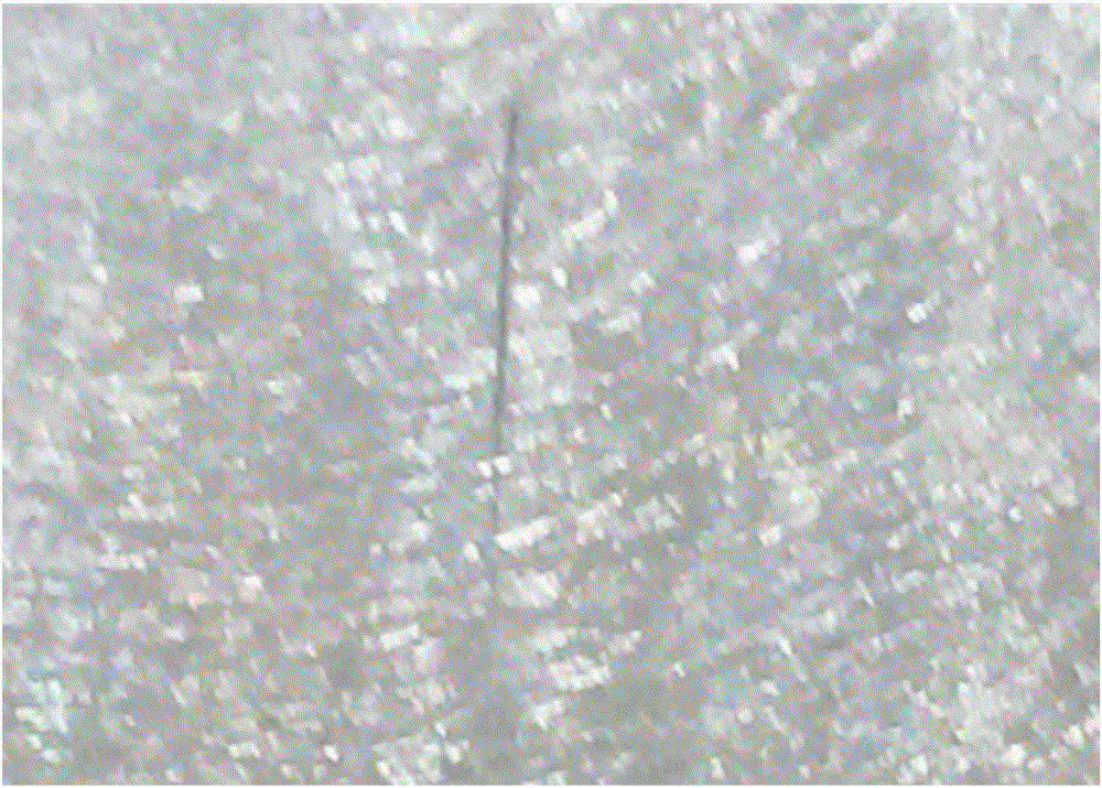
[0034] 1. Cleaning and drying: the finished parts (such as figure 1 shown) for ultrasonic cleaning to remove the excess and oil stains inside the tunnel defect, and then put it in a drying oven for drying at a drying temperature of 60-80°C;

[0035] 2. Determine the welding depth h:

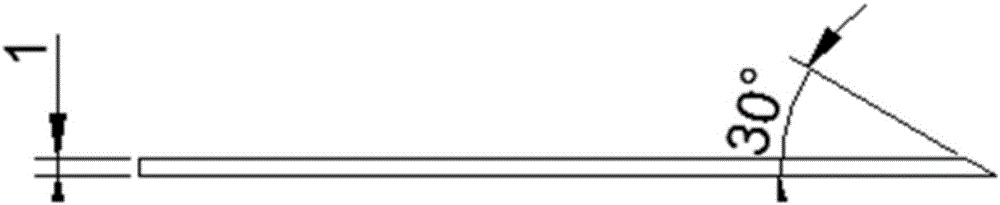
[0036] When the depth of the defect can be determined, the defect depth h0 is determined by inserting the sheet into the defect, h=h0+1mm;

[0037] When the defect depth cannot be determined, the value shall be calculated according to the welding depth of friction stir welding [the length of the stirring needle on the welding head] minus the machining amount;

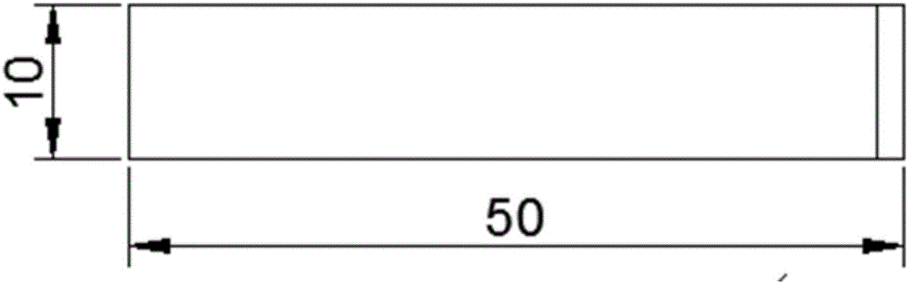
[0038] 3. Installation: Put the parts on the welding workbench, and then install the arc striker and the arc catcher. The distance between the arc striker and the arc catcher is 2-3...

Embodiment 2

[0044] The electron beam repair welding method for friction stir welding tunnel defects implemented in this implementation differs from that of Example 1 in that in step 1, the cleaning liquid for ultrasonic cleaning is alcohol, which can ensure that the oil stains remaining in the tunnel defects during the machining process Wait until it's cleaned.

Embodiment 3

[0046] The difference between the electron beam repair welding method for the friction stir welding tunnel defect implemented in this implementation and the first embodiment is that in step 1, the defect side of the part is facing downward during cleaning to ensure that the excess is easy to fall off.


PUM

PropertyMeasurementUnit
thicknessaaaaaaaaaa
widthaaaaaaaaaa
lengthaaaaaaaaaa

Abstract

The invention discloses an electronic beam repair welding method for friction stir welding tunnel defects, and relates to repair welding technologies, in particular to a repair welding method for the tunnel defects exposed out of an aluminum alloy friction stir welding liquid cooling assembly after finish machining. The electronic beam repair welding method for the friction stir welding tunnel defects achieves repair welding of the tunnel defects exposed out of the aluminum alloy friction stir welding liquid cooling assembly after finish machining, and therefore deformation of a finish machining structure is avoided, product cost is saved, and the product period is shortened. The electronic beam repair welding method for the friction stir welding tunnel defects comprises cleaning, drying, welding depth h determining, mounting, welding program programming, repair welding and machining. The method can be used for repair welding of the tunnel defects, and the market vacancy is filled; the method is applicable to deformation-free repair welding of the aluminum alloy tunnel defects, and belongs to the technical field of material welding.

Description

technical field [0001] The invention relates to a repair welding technology, in particular to a repair welding method for tunnel defects exposed by aluminum alloy friction stir welding liquid cooling components after finishing. Background technique [0002] Friction stir welding technology is widely used in the welding of structures such as aluminum alloy liquid-cooled radiators. For aerospace structures, after friction stir welding is completed, non-destructive testing, such as X-ray flaw detection and ultrasonic flaw detection, is required to check whether there are defects in the welded parts. Friction stir welding is used to repair the parts found to be defective after inspection, so as to ensure that the aerospace structure is free of defects after welding. However, due to the inspection accuracy and judgment error in all non-destructive testing methods, as well as the particularity of the welding structure itself, there is a possibility of missed judgment of welding de...

Claims


Application Information

Patent Timeline
Patent Type & Authority Applications(China)
IPC IPC(8): B23K9/04B23K9/235B23K101/04
CPCB23K9/04B23K9/235B23K2101/04
Inventor 方坤仇晗梁宁李正雷党刚王传伟王国超
Owner CHINA ELECTRONIC TECH GRP CORP NO 38 RES INST
Why Eureka
Try Eureka