
Grinding method of circular tooth cutter CNC grinding machine

A grinding machine and circular tooth cutter technology, which is applied in the field of grinding machines, can solve the problems of difficult processing of circular tooth cutter blades, etc., and achieve the effects of high grinding precision, increased strength and high production efficiency

Active Publication Date: 2019-06-11
马鞍山俊强精密机械设备有限公司
View PDF8 Cites 0 Cited by
  • Summary
  • Abstract
  • Description
  • Claims
  • Application Information

AI Technical Summary

Problems solved by technology

[0007] Aiming at the problem that the existing scalloped knife blades are difficult to process, the present invention provides a scalloped knife CNC grinding machine and its grinding method, which can realize automatic grinding of scalloped knife blades, and the grinding can be completed in one clamping operation, with the advantages of high processing precision, high production efficiency, high yield and low cost

Method used


Image

  • Grinding method of circular tooth cutter CNC grinding machine
  • Grinding method of circular tooth cutter CNC grinding machine
  • Grinding method of circular tooth cutter CNC grinding machine

Examples


Embodiment 1

[0060] This embodiment provides a circular gear cutter CNC grinding machine, its overall shape is as follows Figure 4 As shown, it includes a host and a casing, and a control panel is arranged on the casing. Such as Figure 5 As shown, the main machine includes a machine base, an X-axis part 1, a Y-axis part 2 and a grinding wheel dressing device 4 arranged on the machine base; wherein, the X-axis part 1 includes an X-axis slide table 110 and a The grinding wheel driving device 120 on the platform 110 is used to drive the grinding wheel 122 to rotate in the XZ plane to grind the blade, and the slide table 110 can move in the X-axis direction along the X-axis to adjust the X-axis of the grinding wheel 122 Coordinates; the Z-axis part 3 is set on the Y-axis part 2, and the Z-axis part 3 includes a Z-axis slide table 310 and a workpiece driving device 320 arranged on the Z-axis slide table 310. The workpiece driving device 320 is used for clamping and Drive the blade to rotate...

Embodiment 2

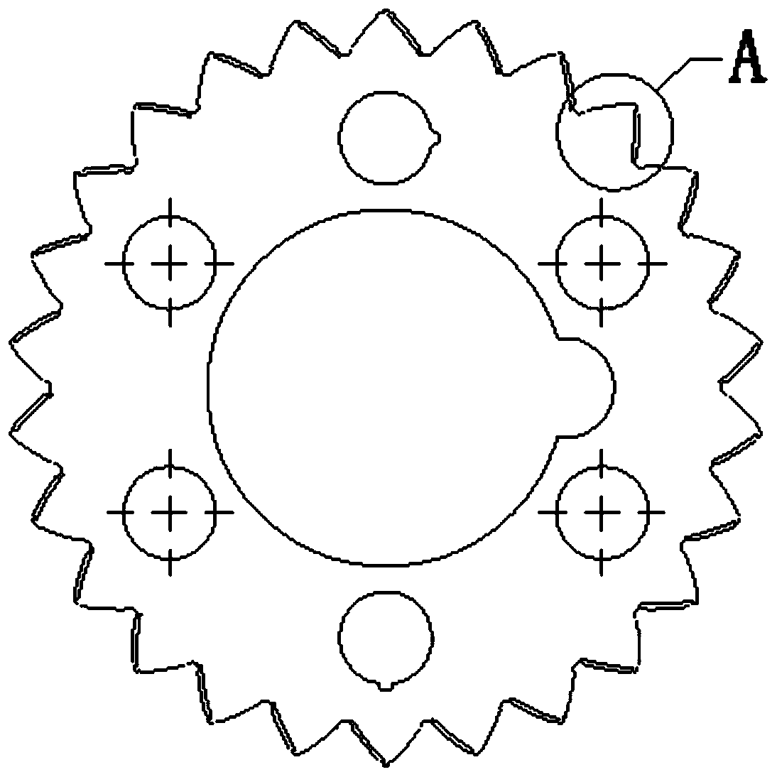
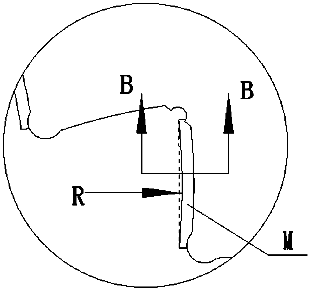
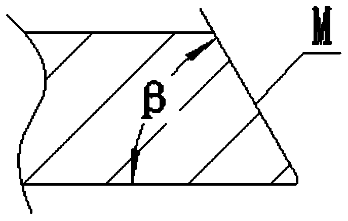
[0069] This embodiment provides a grinding method for a crenated cutter, using the numerically controlled grinder for a crested cutter in Embodiment 1 to grind the edge of the crested cutter, and the processed crested cutter is as follows figure 1 , figure 2 with image 3 As shown, it is necessary to process the blade surface M on the tooth side. The blade surface M is a circular arc surface with a radius of R, and the cutting surface of the blade surface M forms an angle β with the blade surface. In this embodiment, R=37.5mm, β =55°, and the thickness of the circular tooth cutter is b=2mm. The specific operation steps are as follows:

[0070] ① First, install the scalloped cutter to be processed on the fixture of the workpiece driving device 320 to ensure that the surface of the scalloped cutter is level, and drive the scalloped cutter to rotate through the workpiece motor 322 to measure the radial runout and ensure that the radial runout is not greater than 0.02mm; then ...

Embodiment 3

[0079] This embodiment provides a grinding method for a crenated cutter, using the numerically controlled grinder for a crested cutter in Embodiment 1 to grind the edge of the crested cutter, and the processed crested cutter is as follows figure 1 , figure 2 with image 3 As shown, it is necessary to process the blade surface M on the tooth side. The blade surface M is a circular arc surface with a radius of R, and the cut surface at the middle position of the blade surface M forms an angle β with the blade surface. In this embodiment, R=40mm, β=60°, and the thickness of the circular tooth cutter is b=2.5mm. The specific operation steps are as follows:

[0080] ① First, install the scalloped cutter to be processed on the fixture of the workpiece driving device 320 to ensure that the surface of the scalloped cutter is level, and drive the scalloped cutter to rotate through the workpiece motor 322 to measure the radial runout and ensure that the radial runout is not greater t...


PUM

PropertyMeasurementUnit
radiusaaaaaaaaaa
radiusaaaaaaaaaa

Abstract

The invention discloses a round-tooth cutter numerical control grinding machine and a grinding method thereof, and belongs to the field of grinding machines. The grinding machine comprises an X-axis part, a Y-axis part, a Z-axis part and a grinding wheel dressing device. The X-axis part comprises a grinding wheel drive device, and the grinding wheel drive device is used for driving a grinding wheel to rotate in the XZ plane to grind a blade and can move in the X-axis direction so as to adjust the X-axis coordinate of the grinding wheel. The Y-axis part is provided with the Z-axis part. The Z-axis part comprises a workpiece drive device, and the workpiece drive device is used for clamping and driving the blade to rotate and can adjust the Y-axis coordinate and the Z-axis coordinate of the blade. The grinding wheel dressing device is used for driving a dressing wheel to rotate in the XY plane. According to the method, the peripheral face of the grinding wheel is firstly dressed through the dressing wheel, then the vertical height of a round-tooth cutter is adjusted, and finally a cutting edge of the round-tooth cutter is ground. According to the round-tooth cutter numerical control grinding machine and the grinding method, the cutting edge of the round-tooth cutter can be automatically ground, grinding operation can be completed through one-time clamping, and the beneficial effects of being high in machining precision, production efficiency and yield and low in cost are achieved.

Description

technical field [0001] The invention belongs to the technical field of grinding machines, and more specifically relates to a circular-tooth cutter numerical control grinding machine and a grinding method thereof. Background technique [0002] The circular blade is one of the important parts of the slitter equipment. Generally, it is determined which slitter blade to choose according to the type and thickness of the slitting material. Generally, the slitting form of the slitter blade includes square knife slitting and round knife slitting. The square knife slitting is like a razor, the blade is fixed on the knife holder of the slitting machine, and the knife is dropped during the material running, so that the knife cuts the material longitudinally to achieve the purpose of slitting. There are mainly two ways of circular knife slitting: upper and lower disc knife cutting and circular knife extrusion slitting. Round knife slitting is the main slitting method for slitting thi...

Claims


Application Information

Patent Timeline
Patent Type & Authority Patents(China)
IPC IPC(8): B24B3/60B24B41/02B24B47/20B24B53/06
CPCB24B3/60B24B41/02B24B47/20B24B53/062
Inventor 邓兵张祥想
Owner 马鞍山俊强精密机械设备有限公司
Learn More