Cam shaft sealing ring pressing machine

A sealing ring and camshaft technology, applied in the field of mechanical equipment, can solve the problems of poor sealing performance, low production efficiency, no sealing effect, etc., and achieve the effects of ensuring the quality of press-fitting, improving production efficiency, and ensuring sealing performance.

Active Publication Date: 2016-12-07
宁波圣龙智造凸轮轴有限公司
View PDF5 Cites 16 Cited by
  • Summary
  • Abstract
  • Description
  • Claims
  • Application Information

AI Technical Summary

Problems solved by technology

But, the shortcoming that the sealing ring press-fitting device of this structure exists is:
[0003] 1) Since the device presses down the punching head to install the sealing ring into the inner hole of the workpiece, it is not suitable for installing the sealing ring in the sealing groove of the outer peripheral wall at the end of the camshaft; in addition, this The device can only be assembled with one sealing ring at a time, and each assembly needs to be manually picked and placed, and its production efficiency is extremely low;
[0004] 2) The sealing ring is only placed at the orifice of the workpiece before pressing down, and it is not easy to align when pressing in, resulting in improper assembly, which affects the sealing performance of the assembled camshaft;
[0005] 3) Since the camshaft is a slender part, the sealing ring needs to be installed at the end. If there is no positioning device, the camshaft cannot stand stably on the workbench at all. Therefore, the sealing ring pressing device cannot be used for Press-fitting of the sealing ring at the end of the camshaft;
[0006] 4) In addition, when installing the sealing ring on the outer peripheral wall of the camshaft, it is necessary to expand the sealing ring first, and then put it into the sealing groove on the camshaft. However, after the sealing ring is expanded, if it is not restored in time, the sealing ring will Extrusion with the sealing groove will not fit completely, resulting in leakage, resulting in poor sealing performance or even no sealing effect

Method used


Image

  • Cam shaft sealing ring pressing machine
  • Cam shaft sealing ring pressing machine
  • Cam shaft sealing ring pressing machine

Examples


Embodiment Construction

[0042] The present invention will be described in further detail below in conjunction with the accompanying drawings and specific embodiments.

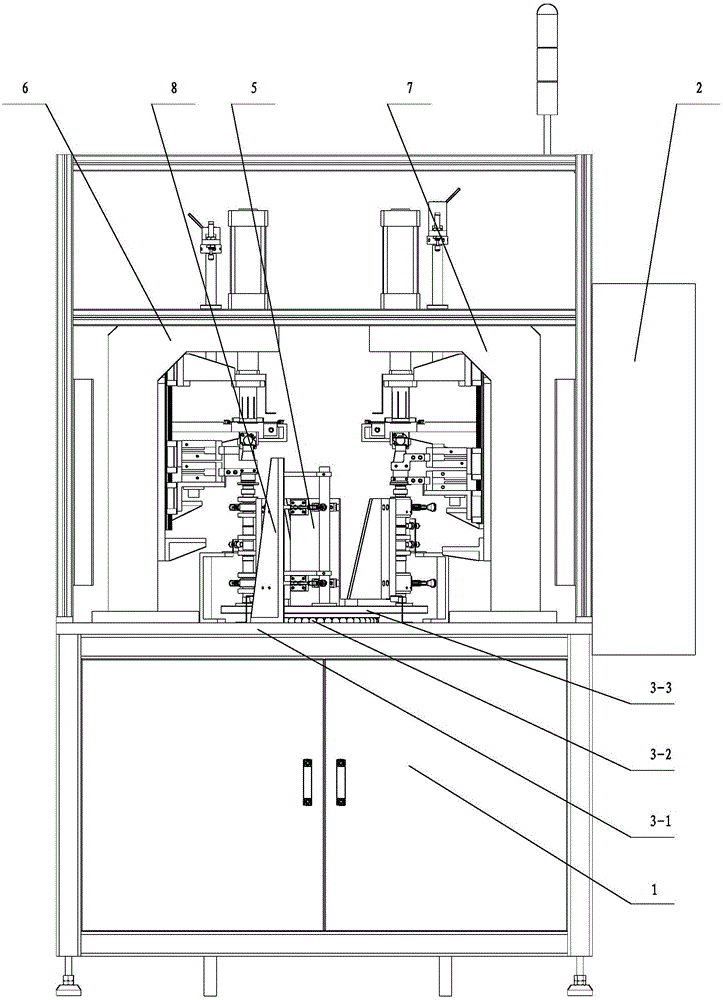
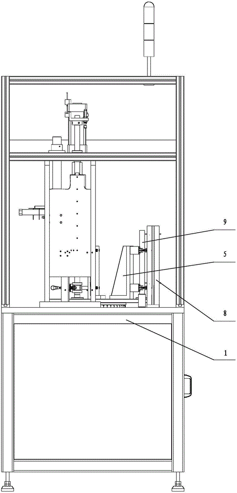
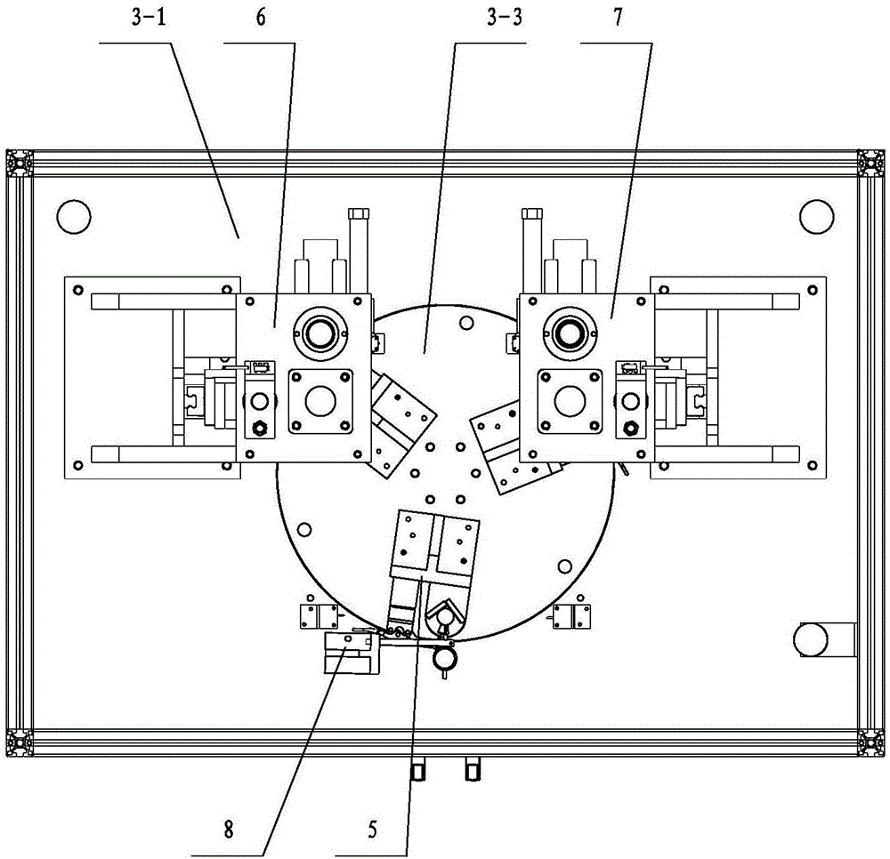
[0043] Depend on Figure 1 to Figure 18 The shown schematic diagram of the structure of the camshaft sealing ring press-fitting machine of the present invention shows that it includes a frame 1, an electric control cabinet 2, a rotary table, a camshaft clamping device, a head sealing ring pressing device and a tail sealing ring pressing device. install the device. Described turntable workbench comprises turntable 3-3, worktable 3-1, transmission mechanism 3-2 and driving mechanism 3-4, and worktable 3-1 is fixedly connected on the frame, and driving mechanism 3-4 It is installed on the bottom surface of the workbench 3-1, and the power output shaft of the driving mechanism 3-4 is connected with the turntable 3-3 through the transmission mechanism 3-2, and the turntable 3-3 is located above the workbench 3-1. The electric control cab...


PUM


Abstract

The invention discloses a cam shaft sealing ring pressing machine. The cam shaft sealing ring pressing machine comprises a rack (1), an electric control cabinet (2), a rotary table type workbench, cam shaft clamping devices, a head sealing ring pressing device and a tail sealing ring pressing device. The three sets of cam shaft clamping devices are arranged and connected to a rotary table (3-3). The head sealing ring pressing device and the tail sealing ring pressing device are arranged on a workbench plate (3-1). The installing position of the head sealing ring pressing device and the installing position of the tail sealing ring pressing device correspond to the positions of the cam shaft clamping devices on the rotary table (3-3). Drive mechanisms of the rotary table type workbench, the head sealing ring pressing device and the tail sealing ring pressing device are electrically connected with the electric control cabinet (2). After the above structure is adopted, cam shaft clamping only needs to be conducted at the position of a feeding clamping station, the pressing machine is started, the station automatically rotates to a head sealing ring pressing station or a tail sealing ring pressing station, operation is very convenient, and therefore the production efficiency is greatly improved.

Description

technical field [0001] The invention relates to the technical field of mechanical equipment, in particular to a camshaft sealing ring press-fitting machine. Background technique [0002] The camshaft is a component in a piston engine that controls the opening and closing of the valves. The main body of the camshaft is a cylindrical rod with approximately the same length as the cylinder group. Several cams for driving the valves are sheathed on the shaft. Sealing ring, because the sealing ring is to be pressed into the sealing groove of the camshaft, and usually the inner diameter of the sealing ring is smaller than the size of the shaft end on the camshaft, so after the sealing ring is squeezed and deformed during the press-fitting process, the The inner diameter of the sealing ring is increased. In the prior art, the seal ring press-fitting of the camshaft is usually a manual assembly by manual operation, and the detection of the seal ring camshaft by a press-fit tool wit...

Claims


Application Information

Patent Timeline
Patent Type & Authority Applications(China)
IPC IPC(8): B25B27/02
CPCB25B27/0028B25B27/026
Inventor 王晨余星徐宁曾夏刚龙周杰朱瑞罗玉龙
Owner 宁波圣龙智造凸轮轴有限公司
Why Eureka
Try Eureka