Multi-station winding mold for manufacturing intermediate pipe and manufacturing method for intermediate pipe

The technology of multi-station and intermediate pipe is applied in the field of multi-station winding mold for manufacturing intermediate pipe and the manufacturing field of intermediate pipe, which can solve the problems of waste of raw materials, low production efficiency and high production cost, so as to reduce production cost and improve usage. Longevity and the effect of reducing scrap rate

Active Publication Date: 2016-12-07
ZHUZHOU TIMES NEW MATERIALS TECH
View PDF5 Cites 3 Cited by
  • Summary
  • Abstract
  • Description
  • Claims
  • Application Information

AI Technical Summary

Problems solved by technology

[0007] When the mandrel in the above-mentioned patent document is processing the intermediate pipe, it can only form one finished intermediate pipe at a time, and the production efficiency is low; in addition, during processing, a finished intermediate pipe needs to cut two angle-changing parts, resulting in The waste of raw materials leads to high production costs

Method used


Image

  • Multi-station winding mold for manufacturing intermediate pipe and manufacturing method for intermediate pipe
  • Multi-station winding mold for manufacturing intermediate pipe and manufacturing method for intermediate pipe
  • Multi-station winding mold for manufacturing intermediate pipe and manufacturing method for intermediate pipe

Examples


Embodiment 1

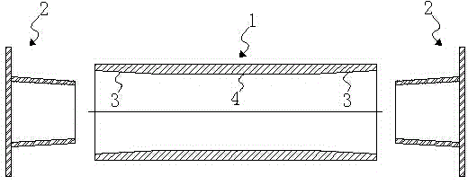
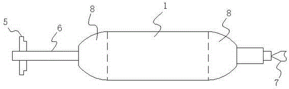
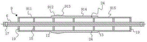
[0052] Embodiment 1: This embodiment provides a three-station winding mold, such as Figure 1 to Figure 6 As shown, a three-station winding mold for manufacturing an intermediate tube includes a main mold cylinder 9 with a main shaft and two hollow auxiliary mold cylinders 10. The main shaft 6 penetrates along the central axis of the main mold cylinder 9 The two ends of the main mold cylinder 9 and the two ends of the main shaft 6 are exposed at the two ends of the main mold cylinder 9, the multi-station winding mold also includes a special-shaped ring 11; the main mold cylinder 9 includes Master mold cylinder one 911, master mold truncated cone body one 912, master mold truncated cone body two 913, master mold cylinder two 914, and master mold cylinder three 915, the small end of the master mold truncated cone body one 912 Set on one end of the main mold cylinder one 911, the big end of the main mold frustum body one 912 is set on the big end of the main mold frustum body two 9...

Embodiment 2

[0078] Embodiment 2: This embodiment provides a four-station winding mold, such as Picture 9 with Picture 10 As shown, compared with Embodiment 1, the difference lies in that: the multi-station winding mold includes two special-shaped circular rings 11, which are special-shaped circular ring one and special-shaped circular ring two, respectively.

[0079] When assembling the four-station winding mold, the special-shaped ring 1 and the special-shaped ring 2 can be assembled and disassembled sequentially on the main mold cylinder 2 of the main mold cylinder.

[0080] After the four-station winding mold is assembled, the outer conical surface of the sub-mold truncated cone body 102 of a sub-mold cylinder and the outer cylindrical surface of the sub-mold cylinder two 103 and the outer cone of the main mold cylinder-912 of the main mold cylinder The conical surface constitutes a station for winding the intermediate tube, using the outer conical surface of the sub-mold truncated cone bo...

Embodiment 3

[0097] Example 3: Such as Picture 11 with Picture 12 As shown, compared with Embodiment 1 and Embodiment 2, the difference is that a main mold is provided between the big end of the main mold frustum body one 912 and the big end of the main mold frustum body two 913 The mold cylinder four 916, that is, one end of the main mold cylinder four 916 is set on the big end of the main mold frustum body one 912, and the other end of the main mold cylinder four 916 is set on the main mold frustum body two 913. On the big end, the main mold cylinder one 911, the main mold truncated frustum body one 912, the main mold truncated frustum body two 913, the main mold cylinder two 914, the main mold cylinder three 915 and the main mold cylinder four 916 are an integrated structure. A hollow cylinder 113 (not shown in the figure) is also provided between the big end of the hollow cone 111 and the big end of the hollow cone 112 of the special-shaped ring, the hollow cone 111, the hollow cone 11...


PUM


Abstract

The invention discloses a multi-station winding mold for manufacturing an intermediate pipe. The multi-station winding mold comprises a main mold cylinder with a spindle, two hollow auxiliary mold cylinders and one or more special-shaped circular rings. The main mold cylinder comprises a first main mold cylinder body, a first main mold circular truncated cone body, a second main mold circular truncated cone body, a second main mold cylinder body and a third main mold cylinder body. Each auxiliary mold cylinder comprises a hollow first auxiliary mold cylinder body, a hollow auxiliary mold circular truncated cone body, a hollow second auxiliary mold cylinder body, a circular-ring-shaped end cover and a hollow round pipe. Each special-shaped circular ring comprises a hollow first circular cone and a hollow second circular cone. During assembling, the one or more special-shaped circular rings are detachably installed on the second main mold cylinder body in a sleeving mode. The two auxiliary mold cylinder bodies are detachably installed at the two ends of the main mold cylinder correspondingly in a sleeving mode in the direction of the two ends of the main mold cylinder. The two ends of the spindle penetrate through end covers of the two auxiliary mold cylinder bodies and the round pipes correspondingly, the two ends of the spindle are exposed to the round pipes of the two auxiliary mold cylinder bodies, and thus a plurality of stations winding the intermediate pipe are formed. Through the multi-station winding mold, a plurality of intermediate pipes can be formed at one time, and thus the cost is reduced.

Description

Technical field [0001] The invention relates to a core mold for manufacturing an intermediate tube of a coupling and a manufacturing method using the core mold, in particular to a multi-station winding mold for manufacturing an intermediate tube and a manufacturing method of the intermediate tube. Background technique [0002] Wind power coupling is an important part of wind power generator set. Its function is to connect gearbox and generator. Its structure is mainly composed of intermediate pipe, flange, torque limiter and tension sleeve. The traditional middle tube is mostly made of alloy steel, but it is gradually eliminated due to poor electrical insulation performance and poor vibration reduction effect. The fiber-reinforced composite middle tube has become a development trend. [0003] Such as figure 1 As shown, during installation, both ends of the fiber-reinforced composite material intermediate pipe 1 need to be bonded to the flange plate 2. Therefore, the inner surfaces ...

Claims


Application Information

Patent Timeline
Patent Type & Authority Applications(China)
IPC IPC(8): B29C53/56B29C53/80
Inventor 黄河王虎谢绍祥盛超李再轲
Owner ZHUZHOU TIMES NEW MATERIALS TECH
Why Eureka
Try Eureka