Low-noise high-speed floating acoustic test device in water tank

An acoustic test and low-noise technology, applied in fluid dynamic tests, measuring devices, transportation and packaging, etc., can solve the problems of unavoidable dragging system, high lower limit frequency, high cost, etc. Effect of device noise cancellation

Active Publication Date: 2016-12-07
NO 719 RES INST CHINA SHIPBUILDING IND
View PDF6 Cites 5 Cited by
  • Summary
  • Abstract
  • Description
  • Claims
  • Application Information

AI Technical Summary

Problems solved by technology

Patent CN201510398686.9 proposes a low-noise, high-speed and large-depth underwater unpowered floating test platform, but this test platform is suitable for unpowered floating tests in large-depth waters such as lakes or seas, and the test period is long and the cost is high. poor repeatability
At present, it is difficult to avoid the mechanical noise generated by the towing system in the towing test in the laboratory pool; in the test in the water tunnel, because the acoustic cavity is too small, the applicable lower limit frequency is too high, and it is difficult to meet the needs of the project for direct noise measurement

Method used


Image

  • Low-noise high-speed floating acoustic test device in water tank

Examples


Embodiment 1

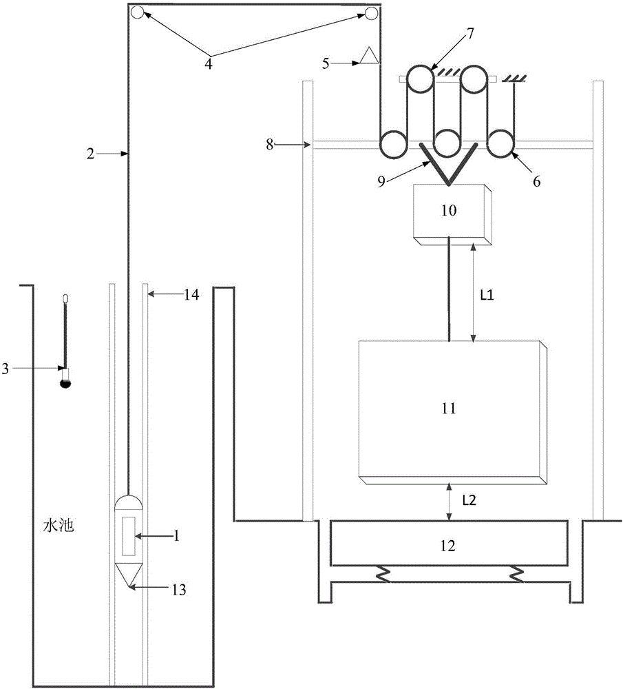
[0022] Such as figure 1 As shown, a low-noise high-speed floating acoustic test device in a pool, the test device includes a test model 1, a soft cable 2, an underwater acoustic measurement device 3, two fixed pulleys 4, an induction speedometer 5, a movable pulley block 6, Fixed pulley block 7, guide mechanism I8, connector 9, weight I10, weight II11 and vibration damping mechanism 12;

[0023] The mass of the weight I10 is less than that of the weight II11, and the outer surfaces of the weight I10 and the weight II11 are covered with rubber plates; the flexible cable 2 is laid with a hydrophobic material; the test model 1 has data collection records instrument to record the attitude, vibration and self-noise generated during the floating process of the test model; the guide mechanism I8 is composed of a horizontal rod and two vertical rods, and the two ends of the horizontal rod are slidingly matched with the two vertical rods and respectively connected with the two vertical...

Embodiment 2

[0031] Embodiment 2, on the basis of Embodiment 1, the test model is fixedly installed inside the streamlined underwater structure 13, and the streamlined underwater structure 13 is fixedly connected with the flexible cable 2, and then the floating test is carried out.

Embodiment 3

[0032] Embodiment 3, on the basis of Embodiment 1, the guide mechanism II14 is fixedly installed in the pool, and the test model 1 is installed inside the streamlined underwater structure 13; the guide mechanism II14 is composed of two vertical rods perpendicular to the water surface, and the guide mechanism The two vertical rods in II 14 are respectively in contact with the streamlined underwater structure 13, and the streamlined underwater structure 13 is fixedly connected with the flexible cable 2; then the floating test is carried out.


PUM


Abstract

The invention relates to a low-noise high-speed floating acoustic test device in a water tank, and belongs to the technical field of underwater aircraft hydrodynamic noise control. The test device comprises a test model, a flexible cable, an underwater acoustic measuring device, two fixed pulleys, an induction type speedometer, a movable pulley unit, a fixed pulley unit, a guide mechanism I, a connector, a weight I, a weight II and a shock absorbing mechanism. When the weight II descends to the shock absorbing mechanism by the aid of the gravity of the weight II, the accelerated speed acquired by the test model under the action of the pulley units is far higher than that of the weight II, and the test model reaches floating speed needed by tests. However, the resistance of a test system is overcome by the gravity of the weight I, the test model keeps the needed speed and floats at constant speed until the weight I descends to contact with the weight II, the test model exactly floats out of a water surface, and near-field noise and free far-field noise characteristics of the test model are acquired by analyzing data recorded by the underwater acoustic measuring device and an internal data acquisition recorder of the test model.

Description

technical field [0001] The invention specifically relates to a test device for testing the steady-state flow-induced noise of an underwater structure when it moves at a constant speed at high speed, and belongs to the technical field of hydrodynamic noise control of underwater vehicles. Background technique [0002] In order to study the vibration, self-noise and radiated noise caused by the fluid excitation when the underwater vehicle is in motion, it has been proposed to carry out the unpowered floating test on the lake or under the sea. The unpowered floating test platform can avoid the power system and propulsion system of the general test platform. Noise generated during the test. Patent CN201510398686.9 proposes a low-noise, high-speed and large-depth underwater unpowered floating test platform, but this test platform is suitable for unpowered floating tests in large-depth waters such as lakes or seas, and the test period is long and the cost is high. Poor repeatabili...

Claims


Application Information

Patent Timeline
IPC IPC(8): B63C11/52G01M10/00
CPCB63C11/52G01M10/00
Inventor 孙国仓陈明李红钢李佩
Owner NO 719 RES INST CHINA SHIPBUILDING IND
Why Eureka
Try Eureka