Replacement and location method of externally prestressed anchor pads for segmental beams

A technology of external prestressing and positioning method, which is applied in the direction of bridges, bridge parts, bridge construction, etc., can solve problems such as the length of the steel bar hook not meeting the design requirements, the long time required for positioning, and the difficulty of increasing the binding of steel bars, etc., to achieve High practical value, large safety factor, and labor-saving effect

Active Publication Date: 2018-06-05
CHINA RAILWAY FIRST GRP CO LTD +1
View PDF6 Cites 0 Cited by
  • Summary
  • Abstract
  • Description
  • Claims
  • Application Information

AI Technical Summary

Problems solved by technology

[0004] First, when the external prestressed anchor plate is positioned, due to the heavy weight of the anchor plate, when the anchor plate is positioned on the rigid skeleton, the anchor plate tube is seriously eccentric (lower head phenomenon), the time required for positioning is long, and the risk factor is large;
[0005] Second, it is required to reserve precise positioning space around the external prestressed pipe when binding the steel bars, which has higher requirements for workers and increases the difficulty of the entire steel bar binding;
[0006] Third, when tying the outermost steel mesh sheet, the length of the steel hook after anchoring cannot meet the design requirements due to the existence of the anchor plate;
[0007] Fourth, due to errors caused by steel tire clamps, hoisting and preliminary positioning, the adjustment space reserved for steel bar binding is not enough to allow the precise positioning of the anchor plate to meet the requirements

Method used


Image

  • Replacement and location method of externally prestressed anchor pads for segmental beams
  • Replacement and location method of externally prestressed anchor pads for segmental beams
  • Replacement and location method of externally prestressed anchor pads for segmental beams

Examples


Embodiment Construction

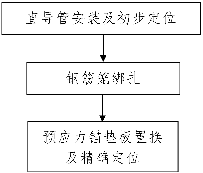
[0035] Such as figure 1 A method for replacing and positioning the external prestressed anchor plate of a segmental beam includes the following steps:

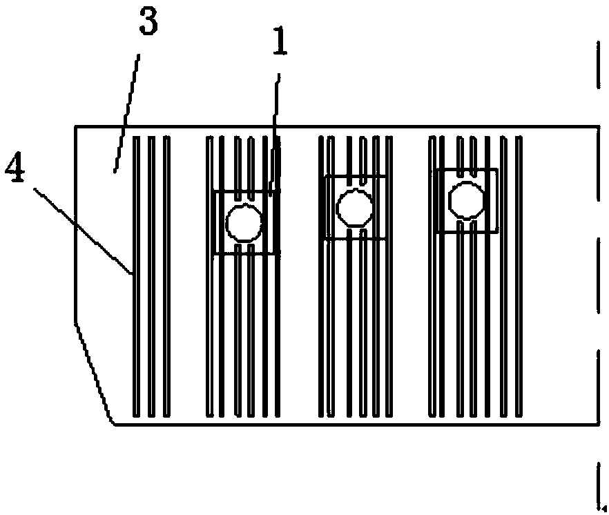
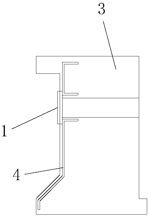
[0036] Step 1. Installation and preliminary positioning of the straight conduit: after the installation of the stiff skeleton for the construction segment beam is completed, according to the pre-designed installation position of the prestressed anchor plate 1 at the end of the segment beam, Straight conduit 2 is installed on the sex skeleton;

[0037] The straight conduit 2 is a straight circular tube arranged horizontally; the inner diameter of the straight conduit 2 is greater than the diameter of the installation hole opened on the prestressed anchor backing plate 1;

[0038] The section beam is a reinforced concrete beam section 3 supported on the bridge pier, the section beam is provided with a reinforcement cage 4, and the stiff skeleton is a support skeleton fixedly installed on the pier;

[0039] Step 2, binding the...


PUM


Abstract

The invention discloses a method for replacing and positioning an external prestressed anchor backing plate of a segmental beam, comprising steps: 1. Installation and preliminary positioning of a straight conduit: after the stiff skeleton used for construction of a segmental beam is installed, according to the pre-designed The installation position of the prestressed anchor backing plate at the end of the section beam is to install a straight conduit on the stiff skeleton; the inner diameter of the straight conduit is greater than the diameter of the installation hole opened on the prestressed anchor backing plate; two, steel cage binding ; 3. Replacement and precise positioning of the prestressed anchor backing plate: take out the straight pipe, install the prestressed anchor backing plate at the installation position of the straight pipe, and adjust the position of the prestressed anchor backing plate until the prestressed anchor backing plate is placed Backing plate installed in place. The method has the advantages of simple steps, reasonable design, convenient construction, and good application effect. It can easily and quickly complete the positioning process of the external prestressed anchor pad, and can effectively reduce the construction difficulty and greatly improve the construction efficiency.

Description

technical field [0001] The invention belongs to the technical field of bridge construction, and in particular relates to a method for replacing and positioning an external prestressed anchor plate of a segmental beam. Background technique [0002] In the process of bridge construction, when constructing the top section of the bridge pier (also called 0# section), the construction process is relatively complicated, and there are many embedded parts on the top section of the pier, including external prestressed embedded parts, permanent finish-rolled rebar Embedded parts, temporary prestressed embedded parts, etc., and when the external prestressed anchor plate is accurately positioned, the construction is difficult and time-consuming, which affects the entire construction period. Wherein, the external prestressed anchor backing plate refers to the prestressed anchor backing plate for the external prestressed steel bars, and the prestressed anchor backing plate is provided wit...

Claims


Application Information

Patent Timeline
Patent Type & Authority Patents(China)
IPC IPC(8): E01D19/14E01D21/00E04G21/12
CPCE01D19/14E01D21/00E04G21/12
Inventor 林俊安静国锋徐宏黄瑞忠陈伟杨学成师忠盼田建伟冯四超刘涛毕张龙赵建民周慧敏
Owner CHINA RAILWAY FIRST GRP CO LTD
Why Eureka
Try Eureka